Chapter 7
Parameter details
-
-
54
Command configuration
(After the setting is changed, the power must be turned on again.)
●
Function
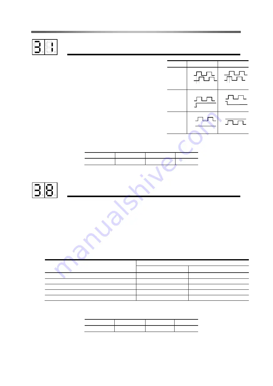
This parameter specifies the pulse input configuration.
0: 2-phase pulse (90-degree phase difference)
1: 1-pulse
A pulse is input for Phase-A input, and a code for
Phase-B input.
2: 2-pulse
A pulse is input for FWD or REV.
The rotary direction indicates operation of the standalone
motor. For AC servo actuator RSF Series, the rotary direction
will be reverse because it is equipped with a HarmonicDrive
®
reduction gear.
For details, refer to
“
Section 3-2, Selecting the command
pulse input configuration".
●
Setting
* After the setting is changed, the power must be turned on again.
Input pin logic setting
(After the setting is changed, the power must be turned on again.)
●
Function
This parameter specifies the logic that enables the functionality of external input signals.
Setting procedure:
Using the table below (in decimal notation), sum up the desired values of the logics to be set. Then,
convert the sum into a hexadecimal number (h).
Example:
To set the error counter clear and forward/reverse inhibit input command to Open and the other to
Close, convert the following into a hexadecimal number (h): 0 + 0 + 4 + 8 + 16 = 28 (dec.). The
resulting value is 1Ch. Set 1C for the parameter.
Signal
Circuit state where the input signal has the meaning
Close
Open
CN1-5 Servo on :S-ON
0
1
CN1-6 Alarm reset : ALM-RST
0
2
CN1-7 Error counter clear :CLEAR
0
4
CN2-31 Forward inhibit :FWD-LMT
0
8
CN2-33 Reverse inhibit :REV-LMT
0
16
●
Setting
Unit
Lower limit
Upper limit
Default
-
0h(0)
1Fh(31)
0h
* After the setting is changed, the power must be turned on again.
Unit
Lower limit
Upper limit
Default
-
0
2
2
設定値
正転指令
逆転指令
0
1
2
90
°
FWD
(A)
REV
(B)
90
°
FWD
(A)
REV
(B)
FWD
REV
FWD
REV
FWD
(Pulse)
REV
(SIGN)
FWD
(Pulse)
REV
(SIGN)


