background image

10


Martin

®

 Exterior Wash

TM

 200 Series User Manual 

Physical installation 


Warning! Read ‘Safety information’ on page 5 before installing the fixture. 

Warning! The safety and suitability of lifting equipment, installation location, anchoring 
method, mounting hardware and electrical installation are the responsibility of the installer. 
All local safety regulations and legal requirements must be observed when installing and 
connecting the Exterior Wash 200 Series. Installation must be carried out by qualified 
professionals only.  

Contact your Martin® supplier for assistance if you have any questions about how to install this product 
safely. 

Fixture location 

Exterior Wash 200 Series fixtures are intended for outdoor use. With an IP rating of 66, they are dust tight 
and able to withstand powerful water jets, but they are not submersible.  

Observe the following limitations in selecting a location:  


Do not immerse the fixture in water or any other fluid. 


Do not install fixtures in a location where flooding may occur. 


Do not allow water to collect on or near the pressure relief valve. Do not install a fixture with the valve 
membrane horizontal so that water can pool on it. 


Ensure sufficient drainage to cope with the heaviest rainfall. Make sure that water can drain away from the 
installation area at least as fast as it can enter it. 


Fixtures require free and unobstructed airflow around them to ensure adequate cooling: do not bury or 
locate in an unventilated space. Allow at least 0.1 m (4 in.) free space around the fixture. 


Install the fixture at least 0.2 m (8 in.) away from the surface to be illuminated and at least 0.1 m (4 in.) 
away from any combustible materials (wood, paper, etc.). Keep it well away from any flammable materials. 


The fixture can become hot. Restrict public access or locate the fixture so that it cannot accidentally be 
touched. 

Mounting the fixture 


Warning! All fasteners used to mount Exterior Wash 200 Series fixtures 
must be corrosion resistant and strong enough to mount the fixture 
safely.  

A washer must be installed directly under the head of each fastener 
when anchoring the yoke base to the installation surface. 

The fixture and yoke can be mounted at any angle. The yoke allows the fixture to be manually panned and 
tilted for beam aiming adjustment. 

The fixture and mounting bracket are manufactured in corrosion-resistant anodized aluminum. Avoid 
mounting the fixture in direct contact with other types of metal, as this can cause galvanic corrosion. When 
fastening to a dissimilar metal surface: 


Use an electrically insulating material (such as rubber or plastic) or coating between the mounting bracket 
and the other metal. 


Use a non-conductive coating such as Delta Seal on fasteners (screws, bolts, washers, etc.) where they 
come into contact with the mounting bracket. 

The fixture’s mounting yoke base must be securely and safely anchored to a stable, static surface, 
pedestal, structural beam or other suitable support. Do not stand the fixture unanchored on a surface or 
leave it where it can be moved or fall over. 

Mounting on a surface 


To anchor the mounting yoke to a wall or other flat surface, use at least three high-strength corrosion-
resistant fasteners that are safe for the application and the environment (recommended minimum 
properties: stainless steel A4-70 grade according to ISO 3506 or steel grade 8.8 according to ISO 898-1). 
Use self-locking nuts. Install washers under all nuts and bolt heads. Make sure that there is a washer 
between each fastener and the yoke base. Ensure that the surface and all fasteners used can support 10 
times the weight of all the fixtures and equipment that they will support. 

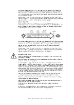
Summary of Contents for Martin Exterior Wash 200 Series

Page 1: ...Exterior Wash 200 Series User manual...

Page 2: ...direct or indirect loss consequential or economic loss or any other loss occasioned by the use of inability to use or reliance on the information contained in this document Martin is a registered trad...

Page 3: ...5 Protecting connections from moisture 15 Connecting to power 15 Control data link 17 Connecting the data link 17 Setup 19 Accessing and navigating the control menus 19 DMX settings 19 Programming a s...

Page 4: ......

Page 5: ...trate the beam Do not look at operating light source Eye injury may result This fixture presents risks of severe injury or death due to burn and fire hazards electric shock and falls if the safety pre...

Page 6: ...ner Shut down power to the entire installation at the main power distribution board and lock out power before carrying out any installation or maintenance work Use only a source of AC power that compl...

Page 7: ...nation light intensity can increase and you should consult a lighting professional for more appropriate safety recommendations Exterior Wash 200 The Exterior Wash 200 is classed Risk Group 3 according...

Page 8: ...ed staring into the light output at less than 14 1 m 46 3 ft from the fixture is not expected Protection from injury Fasten the fixture securely to a fixed surface or structure when in use The fixture...

Page 9: ...over plate to deter unauthorized access They are prepared for hard wiring with 1 8 m 5 9 ft cables for power and data connection Fixture overview 1 Front ring with recessed channel for optional diffus...

Page 10: ...erials The fixture can become hot Restrict public access or locate the fixture so that it cannot accidentally be touched Mounting the fixture Warning All fasteners used to mount Exterior Wash 200 Seri...

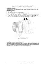
Page 11: ...mps secure the fixture with a safety cable or other secondary attachment that is approved for the weight of the fixture so that the safety cable will hold the fixture if a rigging clamp fails Loop the...

Page 12: ...r Nominal diffuser beam angle Effective beam angle 210 model Effective beam angle 200 220 models None 10 7 Narrow 91610154 10 14 12 Medium 91610153 20 22 21 Wide 91610152 40 41 40 Very Wide 91610151 6...

Page 13: ...can be installed on the front of the fixture in two orientations See illustrations below If a diffuser lens is installed on the front of the fixture install the louver with the profile facing outwards...

Page 14: ...of the snoot fits into the front of the fixture see arrows in illustration below Line up the snoot correctly making sure that screw holes in the snoot line up with threaded holes in the front of the f...

Page 15: ...shut down power to fixtures that is easily accessible and is located close to the fixtures Do not use an external dimming system to supply power to the fixture as this may cause damage to the fixture...

Page 16: ...If you install a power plug on the power cable for temporary use install a grounding type earthed plug with integral cable grip that is rated minimum 277 V 6 A Follow the plug manufacturer s instruct...

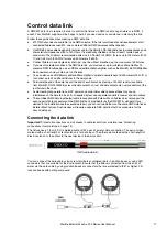
Page 17: ...and the end of each branch by placing a 120 ohm resistor available from Martin P N 04150308 across the data output hot ve and data output cold ve conductors of the last fixture in the chain Avoid crea...

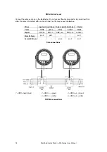
Page 18: ...into contact with a connector shell as this may cause interference Wires Input pair red tube Output pair black tube Shield Color white green white brown black Signal DMX in DMX in DMX out DMX out com...

Page 19: ...ol of the red green blue and white LEDs Since fixtures are uncalibrated slight differences in color and or intensity between different fixtures may be visible in the light output from multiple fixture...

Page 20: ...me type and set to the same DMX control mode may share the same address and control channels if identical behavior is desired The DMX address may be set from the control panel or by RDM To set the fix...

Page 21: ...g when the fixture is mounted upside down flip the display as follows 1 Access the control menu and select DISPLAY SETTINGS Press ENTER 2 Select DISPLAY INVERSE and press ENTER 3 Select YES to invert...

Page 22: ...esistor across data hot and data cold in the data IN connector of the first fixture DMX and RDM signals will override standalone operation in both the host and the client fixtures This means that stan...

Page 23: ...en it is not receiving a control signal from either a DMX controller or a host fixture SHOW MODE Fixture executes its standalone show fixture must be set to HOST If the fixture is set to HOST and it d...

Page 24: ...Press and hold the MENU button to access the control menu 2 If prompted for a password press the arrow buttons to scroll to the current 3 digit password or the service password 111 Press ENTER when th...

Page 25: ...o not use products that contain solvents abrasives or caustic agents for cleaning as they can cause surface damage to the fixture The aluminum housing and front glass can be cleaned with mild detergen...

Page 26: ...t on the PC 3 Connect the Martin Companion Cable to the DMX data link using an XLR connector or screw terminals see Connecting the data link on page 17 for wire colors and pinouts 4 Launch the Martin...

Page 27: ...the ability to control overall intensity level on DMX channel 1 Output is not calibrated Channel Value Function 1 0 255 Dimmer 0 100 2 0 255 Red 0 100 3 0 255 Green 0 100 4 0 255 Blue 0 100 5 0 255 W...

Page 28: ...hannels 1 and 2 Channel 3 provides color temperature control from warm to cold at maximum output When set to a level above 26 channel 3 overrides channels 1 and 2 Channel Value Function 1 0 255 Warm W...

Page 29: ...10 Red 0 255 Manually adjust output Green 0 255 Blue 0 255 White 0 255 Manual Mode 220 Warm White 0 255 Manually adjust output Cold White 0 255 Display Setting Display Inverse No Yes Flip display Disp...

Page 30: ...Config contd DMX State Show Mode Behavior when no DMX control signal present Hold Last Look Black Out Display Lock No Yes Password protect control menu Lock Password 0 999 123 Set user password Facto...

Page 31: ...X link defective Check number of DMX channels required by each fixture and check DMX addresses on fixtures and DMX controller Verify CHANNEL MODE setting Inspect connections and cables Correct poor co...

Page 32: ...00 K 6500 K Control and Programming All models Control systems DMX RDM Setting addressing standalone programming Control panel with OLED display Receiver RS 485 Firmware update Serial upload via DMX l...

Page 33: ...er 12 Medium diffuser 21 Wide diffuser 40 Very wide diffuser 60 Asymmetric diffuser 60 x 12 Photometric Data All models CRI 70 CCT white LEDs 6500 K Exterior Wash 200 Total luminous output 6500 lumens...

Page 34: ...1 5 A 148 W PF 0 99 120 V 60 Hz 1 3 A 146 W PF 0 99 230 V 50 Hz 0 7 A 146 W PF 0 95 277 V 60 Hz 0 6 A 146 W PF 0 88 Exterior Wash 220 100 V 60 Hz 1 6 A 162 W PF 0 99 120 V 60 Hz 1 4 A 160 W PF 0 99 2...

Page 35: ...num P N 90509091 Specifications subject to change without notice For latest product specifications see www martin com Disposing of this product Martin products are supplied in compliance with Directiv...

Page 36: ......

Page 37: ......

Page 38: ......

Page 39: ......

Page 40: ...www martin com...

Reviews: