background image

Operation

40

Signature 2.0

Surround Mode Change

The Signature Series 2.0 offers a number of options for

changing the surround mode. The flexibility of the unit

enables you to use the surround modes programmed at

the factory, to select a mode you prefer for each input

source, or to change the mode at any time during a

listening session.

Factory mode settings are listed in the “Sources” chart in

Appendix A. If you wish to change the mode that is put

into effect any time an input is selected, follow the

instructions on page 28.

When selecting modes it is important to note that the

Movie and Music modes created by the 2.0 processor, 

as well as the Stereo and Mono + modes are available

when an analog source is selected. Some modes are only

available when a digital audio input source is connected

to one of the rear panel 

Optical

or 

Coax Digital

Audio Inputs

‡ °

and AC-3 data is present. Thus,

Dolby Digital or DTS modes are NOT available and 

will not appear in the menus when an analog input is

selected. This is intentional, as these modes will not

function from analog input material.

It is also worth mentioning that different types of digital

data streams that may be used with the 2.0. The con-

ventional PCM digital output from a CD or laser disc

player may be decoded to Mono, Stereo, or Matrix style

surround data. PCM data may also be used for DTS

audio from audio-only discs or specially encoded laser

disc programs. Dolby Digital data may be played back

from a DVD, HDTV, computer sound card, external RF

demodulator, or other source. Most PCM signals are

stereo, limiting their use to the music or movie modes,

as well as Dolby Pro Logic and, of course, Mono +,

stereo or mono.

If a digital input and one of the Dolby Digital or DTS

modes is selected when there is no Dolby Digital or DTS

data present, a warning message will appear. The mode

indication in the front panel 

Information Display

will

flash (Figure FPD-12), indicating an input to mode mis-

match. This will also occur if an analog-only mode (e.g.

any Movie or Music mode, or Dolby Pro Logic) is selected

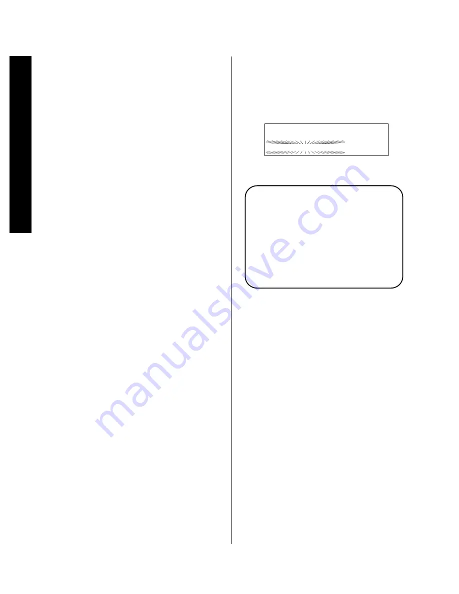
when a digital datastream is present. An alternate mode

will be selected by the 2.0’s processing system and the

unit will automatically switch to it. The alternate mode

name will be displayed in the on-screen message, or it

may be seen by pressing the 

Display

button 

x

for a

full status report (Figure OSD-18).

Figure FPD-12

Figure OSD-18

To remove the warning messages when they appear

simply press the 

Surround Selectors

4 y

until

the suggested mode is in place.

IMPORTANT NOTE: The 2.0’s automatic processing

circuits are constantly examining the digital input signals,

and will cause the front panel display’s mode indication

to flash as a “No Data” indication when no digital data 

is present. You may notice this during pause, scan and

skip modes in most DVD players even though there is a

picture on the screen. This situation is normal and does

not indicate a problem with the disc, player or the 2.0. It

occurs due to the fact that digital data is only available

when the player is running at normal speed.

Depending on the input type (analog, digital AC-3, DTS

or PCM) in use and the mode selected, the mode shown

in the front panel 

Information Display

may flash

when the 2.0 detects other “illegal” input/mode combina-

tions. When this occurs, press the 

Display

button 

x

to view the suggested alternate mode.

V i d e o   1                             V o l

D o l b y   D i g i t a l                   1 0

N O   A C - 3   I n f o

A l t   M o d e :   D o l b y   P r o L o g i c

DVD              Vol

Dolby Digital     10

Summary of Contents for HA160-0004-A

Page 1: ...Printed in the United States Part 1111 HKSIG20 HA160 0004 A...

Page 2: ...2 0 Processor Tuner Owner s Manual...

Page 3: ...Remote Control Operation 12 15 Remote Control Programming 16 18 System Installation 19 21 System Configuration 22 26 Source Configuration 27 32 Advanced Setup 33 36 Operation 37 53 Troubleshooting Gui...

Page 4: ...Staple or clip your original invoice here...

Page 5: ...rticipating stations in your reception area To obtain maximum benefit from the Signature 2 0 s many features we urge you to take a few minutes to read through this manual That will ensure that connect...

Page 6: ...grounding electrode NOTE TO CATV SYSTEM INSTALLER This reminder is provided to call the CATV Cable TV system installer s attention to article 820 40 of the NEC that provides guidelines for proper grou...

Page 7: ...elp This device complies with Part 15 of the FCC Rules Operation is subject to the following two conditions 1 this device may not cause harmful interference and 2 this device must accept interference...

Page 8: ...major dividends in the long term in the form of hours of greater listening pleasure IMPORTANT NOTE Before connecting your new Signature 2 0 you will need to physically locate it in your system To ensu...

Page 9: ...oofer or subwoofer amplifier Connect to inputs of audio power amplifiers Connect to Trigger In jack on Signature Series or other compatible power amplifier Connect AC Power to non switched wall outlet...

Page 10: ...ty is matched between the speaker and amplifier when connections are made 9 Install the batteries in the remote control being careful to observe the and polarity indicators on the remote and the batte...

Page 11: ...e flashing mode is not the one originally selected rather it is the mode automatically selected by the 2 0 to match the input source For example when the Pro Logic mode is selected but a Dolby Digital...

Page 12: ...s to change the surround mode in use Note that the list of modes available is different for digital or analog audio sources 5 Standby LED When this indicator lights in an amber color the 2 0 is in the...

Page 13: ...t have a start or end point to its rotation Volume indications are provided in both the front panel Information Display and the on screen control system see figure OSD 13 on page 38 to provide informa...

Page 14: ...to the Signature 2 0 make certain that the plugs are firmly seated into the jacks This prevents intermittent connections which may interfere with performance DIGITAL AUDIO DATA INPUTS ANTENNA SUB 1 2...

Page 15: ...Record Output Connect this jack to the S Video REC IN input of a VCR S Video Main Output Connect this jack to the S Video input of the TV video monitor projector or display that will be used to view...

Page 16: ...o m r s t u v w x y z Presets a a Main Power On Off b Learn LED c IR Transmitters d Sending LED e Use Learn Switch f Source Power On Off g Source Selection h Simulcast Button i Menu Control Buttons j...

Page 17: ...s explained on pages 17 18 g Source Selection Pressing these buttons will select the input source for the 2 0 It will also activate the transport and numeric control buttons associated with that devic...

Page 18: ...mode or input source is changed or the 2 0 is turned off the adjustment is canceled and the system preset will return To make a permanent change to any of these settings use the Effects Menu as descri...

Page 19: ...gh the list of surround modes that are most appropriate to musical selections c Pressing the Movies button will scroll through the list of surround modes that are most appropriate for movie soundtrack...

Page 20: ...fresh AAA type cells Be certain to observe the correct polarity by noting the and marks on both the inside of the case and on the battery cells It is recommended that both batteries be changed at the...

Page 21: ...transmit a different code when CD is selected as opposed to when VCR is selected The keys that may be programmed with multiple codes are the following All Numeric Keys 0 9 Source Power On Source Powe...

Page 22: ...red using steps 2 through 5 When you have finished programming the remote slide the Use Learn switch e to the left so that it is in the Use position Resetting the Remote Memory In normal operation cod...

Page 23: ...n the section of this manual covering the Sources Menu on page 27 When making audio video connections it is a good idea to note the connection points on the User Worksheet provided in Appendix B For s...

Page 24: ...0 s front panel remote sensor is blocked by cabinet doors or other obstructions an optional external IR sensor may be connected to the IR Input If you are connecting multiple products to the same sens...

Page 25: ...may be fed to compatible devices by connecting the IR Output to the IR Input of other devices When the 2 0 s internal Remote Sensor Window is blocked connect an external sensor to the IR Input or con...

Page 26: ...the room These adjustments will also enable you to use the power of the 2 0 s menu system so that input sources may be grouped and named to suit your requirements Finally there are adjustments and ca...

Page 27: ...manufacturer or experi ment with the best location for a subwoofer in your listening room At least 2 feet At least 6 inches from ceiling Configuring Your System Once the speakers have been installed...

Page 28: ...This information pertaining to the characteristics of the speakers not their brand or model establishes the bass management of the 2 0 To begin the process press the Menu button j and note that the m...

Page 29: ...nd speakers are installed After selecting the Surround speaker type press the Menu Control button i so that Subwoofer is highlighted Use the or Menu Control buttons i to select Yes when a subwoofer is...

Page 30: ...Speaker Distances is highlighted and press the Menu Control button i to move to the next step At the Speaker Dist Adj menu Figure OSD 4 you will enter the information that will permit the 2 0 to auto...

Page 31: ...call the source profile that is being established You may continue to program the profile that is shown or press the Menu Control button i to change to another remote button to be set When the correct...

Page 32: ...is possible however to select another input device for this source but the tuner will not be accessible if the input is used in that fashion As with other menu selection choices use the or Menu Contr...

Page 33: ...trol buttons i until the desired setting is displayed When you have completed the necessary change press the Menu Control button i to enter the setting to the 2 0 s memory and move to the next step In...

Page 34: ...e Signal Level line for the channel being adjusted shows a constant Ref display When one channel has been adjusted repeat the procedure for the other if necessary S e t I n p u t L e v e l s L I n p u...

Page 35: ...lifiers Here the adjust ment is a true volume level change To change the subwoofer trim make certain that Subwfr Trim is highlighted and use the and Menu Control buttons i to adjust the level When the...

Page 36: ...set from center to the left or right by the number after the R L indication with LF indicating a left offset and RT indicating a right offset When the o is on the center vertical line a 0 appears afte...

Page 37: ...actory preset to turn on at a level of 10 If you wish to change that setting press the Menu button j to display the Setup Menu Figure OSD 4 and press the Menu Control button i until Advanced Setup is...

Page 38: ...uted when power is restored and the 2 0 is once again turned on This option is useful to prevent unwanted system operation if the 2 0 is used for unattended VCR recording at late night hours and you d...

Page 39: ...isplay Options menu will appear on the screen Figure OSD 11 Figure OSD 11 The first line On Scrn Sts enables you to prevent the on screen menu messages from appearing on the screen If you do not wish...

Page 40: ...al circumstances The Video Fmt option allows you to choose between the NTSC standard which is used in North America parts of South America and many Asian countries and the PAL system which is used in...

Page 41: ...be a brief display of the status information for the input source that is in use The 2 0 may also be turned on by pressing any of the Source Selection buttons g on the remote To return the 2 0 to the...

Page 42: ...ont panel display is turned on by looking at the right side of the front panel Information Display Figure FPD 4 It may also be viewed as part of the dis play that is part of the status message Figure...

Page 43: ...formation Display will change and display the new source name processing mode and current volume level Figure FPD 4 A message with the source name and surround mode will also appear briefly through th...

Page 44: ...f course Mono stereo or mono If a digital input and one of the Dolby Digital or DTS modes is selected when there is no Dolby Digital or DTS data present a warning message will appear The mode indicati...

Page 45: ...he changing mode on the lower left side of the front panel Information Display or in the upper left corner of the on screen display You may also change the surround mode by pressing the Surround Selec...

Page 46: ...e the Bass Boost setting press the Bass button m and note that the default setting will appear in the on screen display Figure OSD 20 and the front panel Information Display Use the or Menu Control bu...

Page 47: ...i to change the setting to any of the available modes which are described on page 31 You will immediately hear the result of any change and the new center channel mode will be shown in the on screen...

Page 48: ...and the station is transmitting data it will also be shown when the Display button x is pressed Figure OSD 25 See page 48 for complete information on the RDS system T u n e r P S e t S t e r e o 1 0 6...

Page 49: ...ng rate for Dolby Digital audio signals on DVD discs and HDTV broadcasts Data Rate displays the speed with which digital data is transferred from the source player to the 2 0 s digital decoder A 384kb...

Page 50: ...a stereo station is tuned 02 89 9 FM Vol KXXX PUBLIC 10 Stereo Indicator However it may occasionally be necessary to change the tuner to mono reception even when stereo broad casts are being received...

Page 51: ...sage Figure OSD 29 as it is entered Figure FPD 16 90 7 FM Vol 01 10 T u n e r P S e t 2 4 S t e r e o 7 9 0 Figure OSD 29 Within five seconds press the Store button to enter the number to the 2 0 s me...

Page 52: ...o transmit so that you may more easily identify it This is usually the call letters but some stations transmit their 02 89 9 FM Vol KXXX PUBLIC 10 network affiliation or other information In rare case...

Page 53: ...pe PTY search press the Type button This will show the RDS Type Search menu in the on screen display Figure OSD 31 and the word Search will appear on the lower line of the front panel Information Disp...

Page 54: ...i to display the Tuner Menu The menu will differ depending on the frequency band in use One menu will appear when an FM station is currently S e t u p M e n u T u n e r R e c o r d O u t p u t s S o u...

Page 55: ...ID line is highlighted At the ID line press the Menu Control button i and note that a series of underline dashes will appear Figure OSD 36 Next press the or Menu Control buttons i and note that a full...

Page 56: ...r e s e t n u m b e r T h e n p r e s s S T O R E t o s a v e audio from another With the flexibility of the 2 0 it is possible to establish a permanent input source profile that matches different inp...

Page 57: ...the record outputs press the or Menu Control buttons i to move the highlighted video to the input you wish to change Use the or Menu Control button to change the input until the desired source locatio...

Page 58: ...ne This will typically occur when a DVD player is in pause or a fast scan mode as no digital data is typically output unless the disc is playing To confirm that the lack of data is the cause of the er...

Page 59: ...M e n u N O Y e s W A R N I N G A L L S E T T I N G S W I L L B E L O S T A R E Y O U S U R E Follow that instruction by holding the Store button until the Reset Completed message appears briefly on...

Page 60: ...oth remote batteries Slide Use Learn switch to Use Make certain front panel sensor is visible Move unit or antenna away from computers fluores cent lights TVs motors or other electrical appliances Swi...

Page 61: ...e Advanced Settings menu see the Troubleshooting Guide on page 54 Speaker Setup Front Left and Right Small Center Small Surrounds Small Subwoofer Yes Speaker Distances Measurements Feet Front Left and...

Page 62: ...to the factory configuration The Worksheets provide a means for you to record the new settings so that they are available for reference Recording the settings will also make it possible to recreate s...

Page 63: ...right channels of a motion picture Dolby Pro Logic uses special encoding techniques to provide a center channel used mostly for dialog and a surround channel used mostly for effects in addition to th...

Page 64: ...n RF modulated signal so that it would fit within the capacity of the LV format Since the Signature Series 2 0 does not accept RF signals an optional outboard RF to data demodulator is required for us...

Page 65: ...ing signal so that it is sent to the front left and right speakers only DTS 2 Chan or to the front left and right channels and left and right surround channels The center channel is downmixed into the...

Page 66: ...nce Stereo is the only mode available in this group the Stereo button acts as a toggle on off selector One press of the button will put the 2 0 in the Stereo mode and the next press returns you to the...

Page 67: ...gramming Program Type PTY Abbreviation NEWS INFORM SPORTS TALK ROCK CLS ROCK ADLT HIT SOFT RCK TOP 40 COUNTRY OLDIES SOFT NOSTALGIA JAZZ CLASSICAL R B SOFT R B LANGUAGE REL MUSIC REL TALK PERSNLTY PUB...

Page 68: ...ects Menu Figure OSD 8 3 10 2 1 0 1 2 3 4 5 6 7 8 9 20 30k 50 100 200 500 1k 2k 5k 10k 20k 8 6 4 2 0 Hz d B r A Treble Cut This chart using data from a sample Signature 2 0 unit and automated test equ...

Page 69: ...IR Sensor Loop through output via 3 5mm mono mini plug Accessory Trigger 6 12 volt DC via 3 5mm mono mini plug tip positive 150mA maximum Surround Modes Analog Dolby Pro Logic Four Movie Modes Four Mu...

Page 70: ...n 40dB 1kHz RDS Modes Station ID Program Type Radio Text Data Program Type Search Tuner Section AM Frequency Range 520 1710 kHz in 10kHz steps Signal To Noise Ratio 40dB Usable Sensitivity 500 V M Sel...

Page 71: ...essage Power off standby message Volume Control indication Status message with NO AC 3 Info Mute indication messages Status message for Dolby Digital Tuner status messages Tuner status message with ba...

Page 72: ...Safety Information 2 Simulcast Operation 52 Source Configuration Input Name 27 Input Assignment 28 Surround Mode Assignment 28 Source Selection 39 Speakers Configuration Setup 24 Distance Adjust 26 L...

Reviews: