background image

12

INSTALLATION AND CONNECTIONS

Installation and Connections

After unpacking the unit, and placing it on a solid 
surface capable of supporting its weight, you will 
need to make the connections to your audio and video 
equipment.

Audio Equipment Connections

We recommend that you use high-quality  interconnect 
cables when making connections to source equipment 
and recorders to  preserve the integrity of the signals.

When making connections to audio source equipment 
or speakers it is always a good  practice to unplug 
the unit from the AC wall  outlet. This prevents any 
possibility of  accidentally sending audio or transient 
signals to the speakers that may damage them.

Important Note

: In order to clearly identify all 

connectors and simplify nstallation, as per the new 
EIA/CEA-863 standard, all connections are colour 
coded as follows:

For Speakers and Audio In/Outputs: White (Left, 
speakers front) and Red (Right, speakers front). 
For Speakers: Green (Center), Blue (Left Surround) and 
Grey (Right Surround). 
For Audio Output: Purple (Subwoofer). 
For Composite Video In/Outputs: yellow. 
For Digital Audio In/Outputs: Orange.

Connect the analog output of a CD player to the 

1. 

CD 

inputs


7

.

NOTE

: When the CD player has both fixed and variable 

audio outputs it is best to use the fixed output unless 
you find that the input to the receiver is so low that the 
sound is noisy, or so high that the signal is distorted.

Connect the analog Play/Out jacks of a  cassette deck, 

2. 

MD, CD-R or other audio recorder to the 

Tape 

Input

 jacks 

0

. Connect the analog Record/In 

jacks on the recorder to the 

Tape Output

 jacks 

1

 on the AVR.

Connect the output of any digital sources to the 

3. 

appropriate input  connections on the AVR rear 
panel. Note that the 

Optical

 and 

Coaxial 

 digital inputs 

L9

4G

 may be used with 

a Dolby Digital or DTS source or the output of a 
conventional CD, MD or LD player’s PCM (S/P-DIF) 
output. 

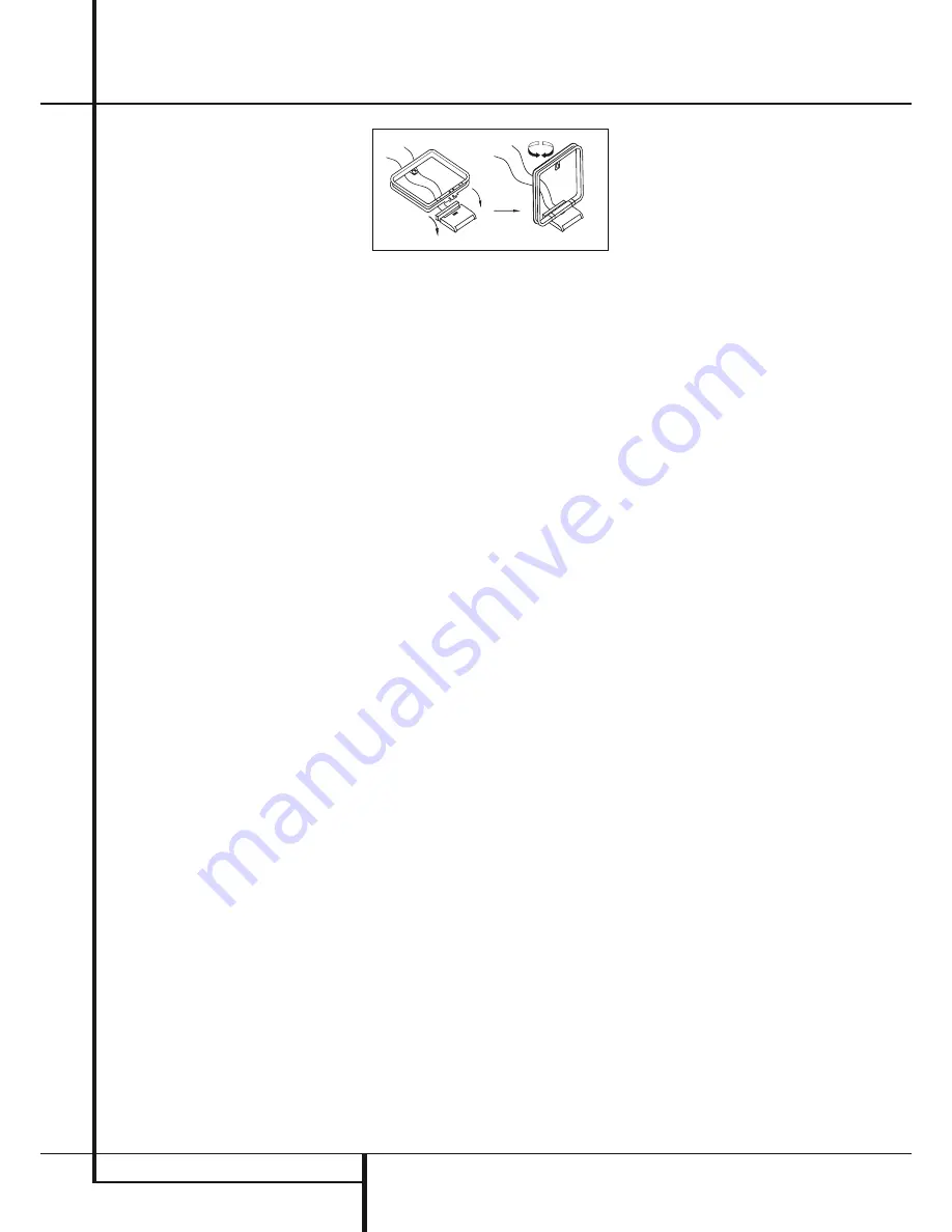
Assemble the AM Loop Antenna supplied with the unit 

4. 

as shown below. Connect it to the 

AM

 and 

GND


screw terminals 

3

.

Connect the supplied FM antenna to the 

5. 

FM 

(75 ohm)

 connection 

6

. The FM antenna may 

be an external roof antenna, an inside powered 
or wire lead antenna or a connection from a cable 
system. Note that if the antenna or  connection 
uses 300-ohm twin-lead cable, you must use 
a 300-ohm-to-75-ohm adapter to make the 
connection.

Connect the front, center and  surround  speaker 

6. 

outputs 

CD

 to the respective  speakers.

To assure that all the audio signals are carried to 
your speakers without loss of clarity or  resolution, 
we suggest that you use high-quality speaker cable. 
Many brands of cable are  available and the choice of 
cable may be  influenced by the distance between your 
 speakers and the receiver, the type of speakers you use, 
 personal preferences and other factors. your dealer or 
installer is a valuable resource to consult in selecting 
the  proper cable.

Regardless of the brand of cable selected, we 
recommend that you use a cable constructed of fine, 
multistrand copper with an area greater than 2 mm

2

.

Cable with an area of 1.5 mm

2

 may be used for short 

runs of less than 4 m. We do not  recommend that you 
use cables with an area less than 1mm

2

 due to the 

power loss and  degradation in  per for mance that will 
occur.

When connecting wires to the speakers, be  certain 
to observe proper polarity. Remember to connect the 
“negative” or “black” wire to the same terminal on both 
the receiver and the speaker. Similarly, the “positive” or 
“red” wire should be connected to like terminals on the 
AVR and speaker.

NOTE

: While most speaker manufacturers adhere 

to an industry convention of using black terminals 
for negative and red ones for positive, some 
manufacturers may vary from this  configuration. 
To assure proper phase and  optimal performance, 
consult the identification plate on your speaker or 
the speaker’s manual to verify polarity. If you do not 
know the polarity of your speaker, ask your dealer 
for advice before proceeding, or consult the  speaker’s 
 manufacturer.

We also recommend that the length of cable used to 
connect speaker pairs be identical. For example, use 
the same length piece of cable to connect the front-
left and front-right or  surround-left and surround-right 
speakers, even if the speakers are a different distance 
from the AVR.

Connections to a subwoofer are normally made via a 

7. 

line level audio connection from the 

Subwoofer 

Output


A

 to the line-level input of a subwoofer 

with a built-in amplifier. When a passive 
subwoofer is used, the connection first goes to a 
power amplifier, which will be connected to one or 
more subwoofer speakers.  
If you are using a powered subwoofer that does 
not have line-level input connections, follow 
the instructions furnished with the speaker for 
connection information.

Note

: Speaker sets with two front satellites and a 

passive subwoofer must be connected to the 

front 

speaker outputs


C

 only rather than to the 

Subwoofer Output


A

.

If an external multi-channel audio source with 5.1 

8. 

outputs such as an external digital  processor/
decoder, DVD-Audio or SACD player is used, 
connect the outputs of that device to the 

6-Channel Direct Inputs


N

.

Video Equipment Connections

Video equipment is connected in the same manner 
as audio components. Again, the use of high-quality 
interconnect cables is recommended to  preserve signal 
quality.

Connect a VCR’s audio and video Play/Out jacks to the 

1. 

Video 2 In jacks


JK

 on the rear panel. The 

Audio and Video Record/In jacks on the VCR should 
be connected to the 

Video 1 Out jacks


4I


on the AVR.

Although any video device may be connected to these 

2. 

jacks, we recommend connecting your TV to the 

Video 1 Audio/Video Input Jacks


2M

 so 

that you may take  advantage of the fact that the 
remote control is preprogrammed with TV product 
codes for the Video 1 device. 
For the same reason, we recommend connecting 
your video recorder, cable TV converter or satellite 
receiver to the 

Video 2 Audio/Video Input 

Jacks


JK

.

Connect the analog audio and video outputs of a 

3. 

DVD to the 

DVD jacks


5C

. This is valid only 

if your DVD player does not have a HDMI Output. 
If a HDMI Output is available on the DVD player, 
connect it to the 

HDMI Inputs


C

. Please note 

that these Inputs are Video only. Audio must be 
connected separately.

Connect the digital audio outputs of a CD, MD or 

4. 

DVD player, satellite receiver, cable box or HDTV 
converter to the appropriate 

Optical

 or 

Coaxial 

Digital Inputs


9L

4G

Remember that the DVD source defaults to the 

Coaxial 1 Digital Input


9

. All other sources 

default to their analog inputs, although any source 
may be assigned to any digital audio input on the 
receiver.

Summary of Contents for AVR/DVD System

Page 1: ...ENGLISH AVR DVD System AVR Audio Video Receiver DVD Digital Versatile Disc Player Owner s Manual...

Page 2: ...ections certain conventions have been used Example bold type indicates a specific remote control or front panel button or rear panel connection jack Example OCR type indicates a message that is visibl...

Page 3: ...or future use Should the unit require maintenance or repair please contact your local Harman Kardon service center Refer servicing to qualified personnel only READ THIS BEFORE OPERATING YOUR UNIT Do n...

Page 4: ...t Up Down F RDS Select G Find Button H A B I DTS Neo 6 Mode Selector J Stereo Mode Selector K Logic 7 Selector L Dim Button M Transport Buttons N Skip Up Down Buttons DWN UP O Night Mode P DTS Digital...

Page 5: ...rmat If this occurs Wait 10 seconds 1 Press the HD M button then the Left Navigation 2 button then the OK button If the video does not recover repeat steps 1 and 2 again 9 Speaker Select Setup Press t...

Page 6: ...ying press this button to zoom the picture so that it is enlarged There are 4 steps to the zoom function each progressively larger Press through each of the zoom stages to return to a normal picture T...

Page 7: ...in the Standby mode it will also turn the AVR on Function List Button Name HK AVR Remote Command AVR TAPE CD AUX VID1 VID2 VID3 HDMI2 HDMI3 HK DVD Remote Command DVD HDMI1 Power ON Power On Power On...

Page 8: ...blue when the unit is on 2 Power Indicator This LED will be illuminated in orange when the unit is in the Standby mode to signal that the unit is ready to be turned on When the unit is in operation th...

Page 9: ...on RDS C Surround Mode Selector Press this button to select from among the available surround mode options for the mode group selected The specific modes will vary based on the number of speakers avai...

Page 10: ...th the receiver to these terminals If an external AM antenna is used make connections to the AM and GND terminals in accordance with the instructions supplied with the antenna 4 Video 1 Audio Outputs...

Page 11: ...eo Inputs Connect these jacks to the PLAY OUT composite jacks on aTV or other video source N 6 Channel Direct Inputs These jacks are used for connection to source devices such as DVD Audio or SACD pla...

Page 12: ...per for mance that will occur When connecting wires to the speakers be certain to observe proper polarity Remember to connect the negative or black wire to the same terminal on both the receiver and t...

Page 13: ...DMI Connections HDMI is the abbreviation for High Definition Multimedia Interface which is quickly becoming the standard connection point between advanced video audio source products and displays part...

Page 14: ...one by pressing the front panel Input Source Selector A until the desired input s name appears in the Main Information Display F The input may also be selected by pressing the appropriate Input Select...

Page 15: ...speakers If a subwoofer is connected to the AVR you have the option to have the front left right main speakers reproduce bass frequencies at all times and have the subwoofer operate only when the AVR...

Page 16: ...remote so that SURR DELAY R and after that SURR DELAY L appears in the Lower Display Line and press the OK Button A Press the the 9 KL Buttons Z on the remote to enter the distance from the surround...

Page 17: ...ecking for speaker placement let the test noise circulate again and listen to see which channels sound louder than the others Using the front left speaker as a reference press the KL buttons Z on the...

Page 18: ...put is selected the last video input used remains routed to the Video Out puts 4I and Video Monitor Output B This permits simultaneous viewing and listening to different sources When aVideo source is...

Page 19: ...Pro Logic II Movies and Dolby 3 Stereo To select a surround mode using the remote press any of the surround mode selector buttons IJKPQc until the desired mode appears As you press the buttons the Su...

Page 20: ...signals are available but there is no discrete center channel signal This will be displayed for Dolby Digital bit streams that have stereo program material A 1 tells you that there is only a mono chan...

Page 21: ...able to adjust the output levels using program material such as a test disc or a selection you are familiar with Additionally the output level for the subwoofer can only be adjusted using this procedu...

Page 22: ...ory for easy recall using the front panel controls or the remote To enter a station into the memory first tune the station using the steps outlined above Then Press the 1 Memory button C on the remote...

Page 23: ...wn buttons 7U the tuner begins to scan the FM band upwards or downwards for the first station that has RDS data that matches the desired selection and acceptable signal strength for quality reception...

Page 24: ...nsor is visible to remote or connect remote sensor Intermittent buzzing in tuner Local interference Move unit or antenna away from computers fluorescent lights motors or other electrical appliances Di...

Page 25: ...dB 1kHz Selectivity 400kHz 70dB Image Rejection 80dB IF Rejection 90dB AM Tuner Section Frequency Range 522 1620kHz Signal to Noise Ratio 45dB Usable Sensitivity Loop 500 V Distortion 1kHz 50 Mod 0 8...

Page 26: ...oped a standard for compressing still images such as photographs JPEG files may be created on a personal computer by importing images from a digital camera or scanning printed photographs These files...

Page 27: ...e DVD player is compatible with multi angle discs that feature is only possible when the disc is specially encoded for multi pleangle play In addition the DVD player is capable of playing back both Do...

Page 28: ...ose Button Press this button to open and close the disc drawer Before pressing this button make sure no objects are blocking the disc drawer 3 IR Remote Receiver This receives infrared signals from th...

Page 29: ...I cable or adapter for the connection to the display In all cases the video display must be HDCP compliant in order to use the HDMI output For best results we do not recommend HDMI connections in exce...

Page 30: ...1kHz sampling MP3 MPEG 1 Audio Layer 3 Linear PCM 44 1 48kHz depending on source if digital output format selected as Bitstream 48kHz if digital output format selected as PCM Digital Format must be s...

Page 31: ...ed at fast speed press Search on the remote Once one of these buttons is pressed the fast search will continue until Play is pressed There are four fast play speeds Each press of the FF Rew M Buttons...

Page 32: ...con at the top of the menu screen General Settings Menu Video Std This setting provides three options Auto PAL and NTSC Use the setting that matches yourTV video standard Select Auto if yourTV support...

Page 33: ...I audio connection Down Sample This setting determines the sampling rate of the PCM 2 channel downmixed signal see above Set this to the highest sampling rate that the connected component can handle N...

Page 34: ...f titles on the disc on the right Chapter This displays the current chapter on the left and the total number of chapters on the disc on the right Time Display This displays the disc s current elapsed...

Page 35: ...edia disc is playing a special screen will appear Repeat Play The DVD player offers several repeat functions for CDs that allow you to take advantage of the capacity of the unit for unattended playbac...

Page 36: ...he screen and the titles of the MP3 files will appear on the right of the screen The player will automatically begin playing all of the MP3 files in the selected folder If the root folder does not con...

Page 37: ...o will replace the folder information on the left To view the selected photo press the OK Button A or the Play Button M The photo will show on the screen and the player will display all the remaining...

Page 38: ...audio playback on DVD discs during fast or slow modes Picture is distorted or jumps during fast forward or reverse play MPEG 2 decoding It is a normal artifact of DVD playback for pictures to jump or...

Page 39: ...A 91329 USA 2010 Harman International Industries Incorporated All rights reserved Harman Kardon is a registered trademark of Harman International Industries Incorporated registered in the United State...

Page 40: ...Harman Consumer Incorporated 8500 Balboa Boulevard Northridge CA 91329 USA 2010 Harman International Industries Incorporated All rights reserved www harmankardon com Part no 950 0324 001...

Reviews: