


Page 7
For technical questions, please call 1-800-444-3353.
SKU 68387 & 68388
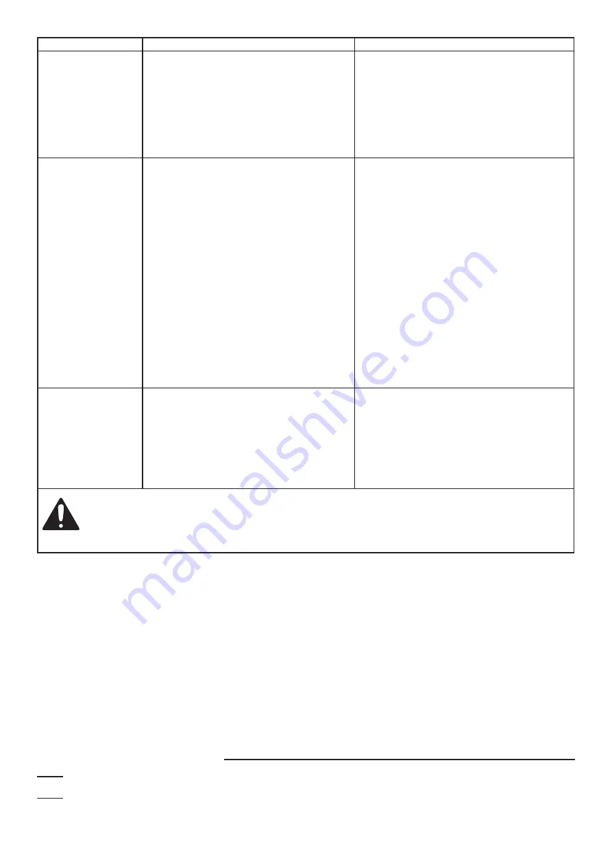
Problem
Cause
Solution
Water is full of
bubbles at outlet
1. Pumping bubbles temporarily as
air is purged after initial setup.
2. Leak in suction side of pump system.
3. Well is gaseous.
4. Water level below suction
inlet of foot valve.
1. Temporary self-remedying issue.
2. Check for and fix leaks.
3. Install a sleeve in the well.
4. Lower suction line into water
and re-prime. If water is deeper
than Maximum Well Depth, then a
deep well pump may be needed.
Motor runs, but water
is not pumping
1. Improper priming.
2. Air leakage.
3. Vertical lift too high.
4. Water level below suction inlet
of foot valve.
5. Frozen pipes.
6. Foot valve in dirt or sand.
7. Foot/check valve clogged.
8. Pressure switch is set too low.
1. Prime the pump by pouring clean
water into the Priming Inlet.
2. Check all pipes and joints in the suction
line for air leakage using soapy water.
3. Reduce vertical lift to within specifications.
See Installation on page 3.
4. Lower suction line into water
and re-prime. If water is deeper
than Maximum Well Depth, then a
deep well pump may be needed.
5. Thaw the pipes. Bury pipes below
freeze line/insulate pipes.
6. Raise foot valve to clean water level.
7. Clean or replace foot/check valve.
8. Have the pressure switch
adjusted by qualified technician
(30 PSI Start, 50 PSI Stop).
Pump does
not shut-off
1. Pressure switch contacts welded together.
2. Fixture (toilet, faucet, etc.) open or leaking.
3. Impeller is clogged.
4. Tank bladder pressure is too low.
5. Pipeline leakage.
6. Foot/check valve leaks water back to well.
1. Have the pressure switch replaced
by a qualified technician.
2. Close or repair fixture.
3. Clean impeller.
4. Inflate to 28 PSI.
5. Repair pipeline.
6. Replace foot/check valve.
Follow all safety precautions whenever diagnosing or servicing the pump.
Disconnect power supply before service.
Do not disassemble the pump or motor as this will damage the water seals.
All repairs should be performed by a qualified technician.
PLEASE READ THE FOLLOWING CAREFULLY
THE MANUFACTURER AND/OR DISTRIBUTOR HAS PROVIDED THE PARTS LIST AND ASSEMBLY DIAGRAM
IN THIS MANUAL AS A REFERENCE TOOL ONLY. NEITHER THE MANUFACTURER OR DISTRIBUTOR
MAKES ANY REPRESENTATION OR WARRANTY OF ANY KIND TO THE BUYER THAT HE OR SHE IS
QUALIFIED TO MAKE ANY REPAIRS TO THE PRODUCT, OR THAT HE OR SHE IS QUALIFIED TO REPLACE
ANY PARTS OF THE PRODUCT. IN FACT, THE MANUFACTURER AND/OR DISTRIBUTOR EXPRESSLY
STATES THAT ALL REPAIRS AND PARTS REPLACEMENTS SHOULD BE UNDERTAKEN BY CERTIFIED AND
LICENSED TECHNICIANS, AND NOT BY THE BUYER. THE BUYER ASSUMES ALL RISK AND LIABILITY
ARISING OUT OF HIS OR HER REPAIRS TO THE ORIGINAL PRODUCT OR REPLACEMENT PARTS
THERETO, OR ARISING OUT OF HIS OR HER INSTALLATION OF REPLACEMENT PARTS THERETO.
Record Product’s Serial Number Here:
Note:
If product has no serial number, record month and year of purchase instead.
Note:
Some parts are listed and shown for illustration purposes only
and are not available individually as replacement parts.
Brought to You by www.snapwhole.com


