background image

Page 4

For technical questions, please call 1-800-444-3353.

SKU 68387 & 68388

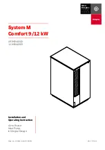
1.  The illustration below shows an example of a proper 

shallow well pump installation.  The total suction lift 

(vertical well lift + length of off-set line) must 

not exceed Maximum Well Depth.

Foot 

Valve

Check 

Valve

Well 

Seal

Shallow 

Well Pump

To 

Household 

Water 

System

Standing Water Level

(With Well Pump Off)

Pumping Water Level

 (with Well Pump Operating)

Outlet Water 

Level

Vertical W

ell Lift

Head

SLOPE SLIGHTLY DOWNWARD TO WELL

Length of off-set line

(Add when calculating total 

suction lift due to friction.)

Figure C:  Pump Setup Example

Note:

 This pump is intended for shallow well application 

only and is not intended to be used as a booster pump.

Note:

 For optimal performance, install the pump 

as close to the well head as possible.

2.  Install a Foot Valve at the bottom of 

the suction pipe.  The Foot Valve must be 

under the Pumping Water Level, the level that 

the water falls to when the pump operates.

3.  Install a sterile Well Seal at the top of the suction 

pipe to keep the well clean.  Protect from 

rust inside a frost-proof enclosure.

4.  Intake and discharge pipes must 

be at least 1 IN. in diameter.

5.  Lay an off-set line from the well to the structure 

the pump will be installed in.  The off-set line should 

slope slightly towards the well (see Figure C).  

Systems with longer off-set lines should use 

larger diameter pipe to improve efficiency.

6.  Install the pump on a rigid, level, dry platform. 

This platform must provide a solid, level surface 

that is capable of supporting the weight of 

the pump and attached piping filled with water.  

Do not allow water to contact the pump’s housing.

CAUTION:  

DO NOT INSERT fittings into the Intake 

Hole farther than 1/2 IN.; this can DAMAGE the Pump, 

diminish Pump functions, and/or STOP water flow.

7.  Keep the Head, the height that the pump discharge 

must push water before discharge, to a minimum.  

The Vertical Well Lift, Off-set Line Length, and Head 

added together must be less than Maximum Lift to 

have flow at output.  Effective flow decreases to 

0 GPH as Maximum Lift reaches its maximum.

8.  For your protection, the power outlet used should 

have a Ground Fault Circuit Interrupter (GFCI). 

Have it installed by a qualified electrician. 

Keep power line away from water.

9.  The inlet and discharge lines should not be 

wedged or stressed in a way that puts strain 

on the pump.  Do not support the pump 

with the inlet or discharge lines.

Brought to You by www.snapwhole.com

Summary of Contents for PacificHydrostar 68387

Page 1: ... as soon as possible Visit our website at http www harborfreight com Copyright 2011 by Harbor Freight Tools All rights reserved No portion of this manual or any artwork contained herein may be reproduced in any shape or form without the express written consent of Harbor Freight Tools Diagrams within this manual may not be drawn proportionally Due to continuing improvements actual product may diffe...

Page 2: ...emical known to the State of California to cause cancer and birth defects or other reproductive harm Wash hands after handling California Health Safety Code 25249 5 et seq 10 The warnings precautions and instructions discussed in this instruction manual cannot cover all possible conditions and situations that may occur It must be understood by the operator that common sense and caution are factors...

Page 3: ...red by a certified electrician Areas of use This pump is designed for use as a well pump Discharge hidden Intake Pressure Gauge Priming Inlet Air Valve hidden Figure A 68387 Components Discharge Intake Pressure Gauge Priming Inlet Air Valve hidden Figure B 68388 Components WARNING TO PREVENT SERIOUS INJURY FROM ELECTRIC SHOCK Install indoors or in weather proof well house only This Pump is non sub...

Page 4: ... pipes must be at least 1 IN in diameter 5 Lay an off set line from the well to the structure the pump will be installed in The off set line should slope slightly towards the well see Figure C Systems with longer off set lines should use larger diameter pipe to improve efficiency 6 Install the pump on a rigid level dry platform This platform must provide a solid level surface that is capable of su...

Page 5: ...me it by filling it with clean water through the Priming Inlet 4 This is a self starting pump that uses a pressure switch Once the power cord is connected the pump can start at any time Do not handle or perform maintenance on the pump if the power cord is plugged in 5 After reading these instructions consider the following points before starting the pump a Verify that the delivery pipe is properly...

Page 6: ...nd seals 5 Clean screen Only a low volume of water flows 1 Inlet pipe is too small 2 Liquid is too dirty 3 Lifting height exceeded 4 Tank s rubber bladder under inflated 5 Piping corroded causing friction 1 Increase pipe diameter 2 Clean screen frequently 3 Reduce lifting height 4 Inflate to 28 PSI 5 Replace piping with plastic where possible Motor overheats often 1 Extension cord too long or wire...

Page 7: ...let faucet etc open or leaking 3 Impeller is clogged 4 Tank bladder pressure is too low 5 Pipeline leakage 6 Foot check valve leaks water back to well 1 Have the pressure switch replaced by a qualified technician 2 Close or repair fixture 3 Clean impeller 4 Inflate to 28 PSI 5 Repair pipeline 6 Replace foot check valve Follow all safety precautions whenever diagnosing or servicing the pump Disconn...

Page 8: ...ase 1 24 Rear Cover 1 25 Bolt 4 26 Fan Cover 1 27 Fan 1 28 Wire Nut 1 29 Wire Gasket 1 Part Description Qty 30 Connection Box Base 1 31 Fixture 1 32 Screw 2 33 Screw 4 34 Connection Box Top 1 35 Screw 2 36 O ring 2 37 Seal Ring 1 38 Capacitor 1 39 Screw 2 40 Hex Nut 3 41 Spring Washer 3 42 Flat Washer 9 43 Terminal 1 44 Lock Washer 1 45 Waterproof Seal 1 46 Bolt 2 47 Flat Washer 2 48 Spring Washer...

Page 9: ...Page 9 For technical questions please call 1 800 444 3353 SKU 68387 68388 68387 Assembly Diagram Brought to You by www snapwhole com ...

Page 10: ... 25 Fan Cover 1 26 Nut 1 27 Cable Jacket 1 28 Connection Box Base 1 29 Fixture 1 30 Screw 2 Part Description Qty 31 Screw 6 32 Spring Washer 9 33 Flat Washer 13 34 Connection Box Cover 1 35 Screw 2 36 O ring 1 37 Seal Ring 1 38 Capacitor 1 39 Hex Nut 3 40 Terminal 1 41 Lock Washer 1 42 Pad 1 43 Hex Nut 2 44 Spring Washer 2 45 Flat Washer 2 46 Flat Washer 2 47 Hex Bolt 2 48 Valve Cab 1 49 Flat Wash...

Page 11: ...Page 11 For technical questions please call 1 800 444 3353 SKU 68387 68388 68388 Assembly Diagram Brought to You by www snapwhole com ...

Page 12: ...to you THIS WARRANTY IS EXPRESSLY IN LIEU OF ALL OTHER WARRANTIES EXPRESS OR IMPLIED INCLUDING THE WARRANTIES OF MERCHANTABILITY AND FITNESS To take advantage of this warranty the product or part must be returned to us with transportation charges prepaid Proof of purchase date and an explanation of the complaint must accompany the merchandise If our inspection verifies the defect we will either re...

Reviews: