background image

7

3.  Check existing outlet box (not included) to ensure it is 

     securely fastened to at least two points in a structural 

     ceiling member and can support the full weight of the 

     fan. Once verified, install mounting bracket (A) to the 

     outlet box using the screws and washers provided with 

     the outlet box. 

INITIAL INSTRUCTIONS 

Lowes.com/harborbreeze

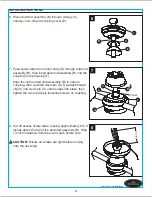
4.  Remove the motor body (G) from the protective plastic 

     bag and take the lower packing pad out of the carton. 

     Place the motor body (G) into the packing pad with the 

     bottom of each motor facing up. Remove the motor 

     screws (CC) and motor blocks from each motor of motor 

     body (G). Discard motor blocks and save the motor 

     screws (CC) for later use. 

Hardware Used

x 6

CC

Motor Screw

5.  Remove hairpin clip (V) and clevis pin (U) from the top 

     housing (F) preassembled to motor body (G). Retain for 

     later use. 

3

Open End

A

A

Note: 

If using the angel mount, make sure open end of 

mounting bracket (A) is installed facing the higher point 

of the ceiling.  

Note: 

Make sure to keep loose hardware separate to 

avoid confusion during installation 

Note: 

Make sure to keep loose hardware separate to 

avoid confusion during installation. 

Loosen the two screws preassembled in coupling on top 

housing (F), but do not remove them. 

DANGER:

 A loose outlet box can cause the fan to 

wobble and increase the fan's potential to fall, which 

could result in serious injury or death. 

4

Motor Block

CC

V

U

G

F

U

Screw

5

Summary of Contents for L0982

Page 1: ...BREEZE II CEILING FAN Questions problems missing parts Before returning to your retailer call our customer service department at 1 800 643 0067 8 a m 6 p m EST Monday Thursday 8 a m 5 p m EST Friday...

Page 2: ...Wiring Instructions Final Instruction Operating Instructions Care and Maintenance Limited Lifetime Warranty Troubleshooting Replacement Parts List Safety Information Package Contents Hardware Contents...

Page 3: ...J Fan Switch Cover K Fan Finial L Light Kit Lowes com harborbreeze 2 M Bulb 1 1 N O P Glass Shade Light Finial Cap Light Finial 1 2 Q Switch Housing preassembled on Motor Body G 1 R Bottom Housing pre...

Page 4: ...d so there is at least 1 64 ft between the bulb and any illuminated surface For supply connections if the conductor of a fan is identified as a grounded conductor then it should be connected to a grou...

Page 5: ...as a tag to the service panel Do not use bulbs having a wattage greater than the maximum value stated on the fixture and in this manual Using a higher wattage bulb than specified will increase fixture...

Page 6: ...r higher For taller ceilings you may want to use a longer downrod not included B Angle Mounting Angle style mounting is best suited for angled or vaulted ceilings A longer downrod is sometimes necessa...

Page 7: ...r body G Discard motor blocks and save the motor screws CC for later use Hardware Used x 6 CC Motor Screw 5 Remove hairpin clip V and clevis pin U from the top housing F preassembled to motor body G R...

Page 8: ...Re attach hairpin clip V into clevis pin U until it snaps into place then tighten the two previously loosened screws on coupling 8 Cut off excess fixture wires leaving approximately 6 to 9 inches abov...

Page 9: ...o in the following steps stop immediately A professional electrician is recommended to determine proper wiring WARNING If you feel that you do not have enough electrical wiring knowledge or experience...

Page 10: ...e using wire connector supplied Securely connect the fan BLACK and BLUE wires to the supply BLACK wire using wire connector supplied 3 Wrap electrical tape not included around each wire connector and...

Page 11: ...Step 4 Page 7 J FINAL INSTRUCTIONS Lowes com harborbreeze NOTE 2 3 C I Slide canopy cover D over the mounting screws visible in canopy C Rotate canopy cover D clockwise until it locks into place You...

Page 12: ...f motor body G securing with fan finial K Repeat for the other motor of motor body G 6 Remove three set screws preinstalled on bottom housing R of motor body G and save them for later use Q J K G 5 G...

Page 13: ...uide the threaded rod and pull chain through the appropriate holes on the light finial cap O Secure it with light finial P 9 9 L N O P 8 Align the cutout on the light kit L with the reverse switch on...

Page 14: ...iddle of bottom housing R and disassemble bottom housing R from motor body G Save screw for later use Remove the bell mouth nut from pull chain and pass the pull chain leg throuth the round hole on th...

Page 15: ...removed step 6 page 12 Tighten securely 15 14 Attach the 9 pin connector preassembled on bottom housing R to the 9 pin connector from motor body G Then re attach the bottom housing R to the motor bod...

Page 16: ...ise rotation creates an upward airflow which moves hot air from the ceiling Push the reverse switch located on motor body G RIGHT and see a SNOWFLAKE icon 2 NOTE Turn off and wait for fan to stop befo...

Page 17: ...y light bulb installation 7 Make sure light bulb is tight in socket and does not touch on glass shade 8 Glass is not secure 8 Secure the glass 1 Hanger bracket and or ceiling outlet box is not securel...

Page 18: ...the ceiling fan by accident misuse or improper installation or by affixing accessories not produced by this warranty are at the purchaser s own responsibility The manufacturer assumes no responsibili...

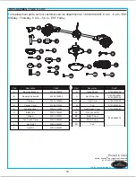
Page 19: ...n Part A Mounting Bracket A102 0075070 B Downrod Assembly A103 0156293 C Canopy A101 0162293 D Canopy Cover A108 0013293 E Coupling Cover A126 0114293 H Blade Iron A143 0159293 I Blade A141 0331001 J...

Reviews: