background image

TABLE OF CONTENTS

2

Preparation ........................................................................................................................

Initial Instructions ............................................................................................................... 

Wiring Instructions .............................................................................................................

Final Instruction ................................................................................................................

Operating Instructions ......................................................................................................

Care and Maintenance .....................................................................................................

Limited Lifetime Warranty ................................................................................................. 

Troubleshooting ................................................................................................................

Replacement Parts List ....................................................................................................

Safety Information ............................................................................................................. 

Package Contents .............................................................................................................

Hardware Contents ............................................................................................................

 4

  3

  4

 5

 6

 9

 10

 16

 17

17

 18

19

Lowes.com/harborbreeze

Summary of Contents for L0982

Page 1: ...BREEZE II CEILING FAN Questions problems missing parts Before returning to your retailer call our customer service department at 1 800 643 0067 8 a m 6 p m EST Monday Thursday 8 a m 5 p m EST Friday...

Page 2: ...Wiring Instructions Final Instruction Operating Instructions Care and Maintenance Limited Lifetime Warranty Troubleshooting Replacement Parts List Safety Information Package Contents Hardware Contents...

Page 3: ...J Fan Switch Cover K Fan Finial L Light Kit Lowes com harborbreeze 2 M Bulb 1 1 N O P Glass Shade Light Finial Cap Light Finial 1 2 Q Switch Housing preassembled on Motor Body G 1 R Bottom Housing pre...

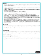
Page 4: ...d so there is at least 1 64 ft between the bulb and any illuminated surface For supply connections if the conductor of a fan is identified as a grounded conductor then it should be connected to a grou...

Page 5: ...as a tag to the service panel Do not use bulbs having a wattage greater than the maximum value stated on the fixture and in this manual Using a higher wattage bulb than specified will increase fixture...

Page 6: ...r higher For taller ceilings you may want to use a longer downrod not included B Angle Mounting Angle style mounting is best suited for angled or vaulted ceilings A longer downrod is sometimes necessa...

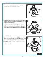
Page 7: ...r body G Discard motor blocks and save the motor screws CC for later use Hardware Used x 6 CC Motor Screw 5 Remove hairpin clip V and clevis pin U from the top housing F preassembled to motor body G R...

Page 8: ...Re attach hairpin clip V into clevis pin U until it snaps into place then tighten the two previously loosened screws on coupling 8 Cut off excess fixture wires leaving approximately 6 to 9 inches abov...

Page 9: ...o in the following steps stop immediately A professional electrician is recommended to determine proper wiring WARNING If you feel that you do not have enough electrical wiring knowledge or experience...

Page 10: ...e using wire connector supplied Securely connect the fan BLACK and BLUE wires to the supply BLACK wire using wire connector supplied 3 Wrap electrical tape not included around each wire connector and...

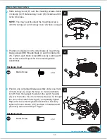
Page 11: ...Step 4 Page 7 J FINAL INSTRUCTIONS Lowes com harborbreeze NOTE 2 3 C I Slide canopy cover D over the mounting screws visible in canopy C Rotate canopy cover D clockwise until it locks into place You...

Page 12: ...f motor body G securing with fan finial K Repeat for the other motor of motor body G 6 Remove three set screws preinstalled on bottom housing R of motor body G and save them for later use Q J K G 5 G...

Page 13: ...uide the threaded rod and pull chain through the appropriate holes on the light finial cap O Secure it with light finial P 9 9 L N O P 8 Align the cutout on the light kit L with the reverse switch on...

Page 14: ...iddle of bottom housing R and disassemble bottom housing R from motor body G Save screw for later use Remove the bell mouth nut from pull chain and pass the pull chain leg throuth the round hole on th...

Page 15: ...removed step 6 page 12 Tighten securely 15 14 Attach the 9 pin connector preassembled on bottom housing R to the 9 pin connector from motor body G Then re attach the bottom housing R to the motor bod...

Page 16: ...ise rotation creates an upward airflow which moves hot air from the ceiling Push the reverse switch located on motor body G RIGHT and see a SNOWFLAKE icon 2 NOTE Turn off and wait for fan to stop befo...

Page 17: ...y light bulb installation 7 Make sure light bulb is tight in socket and does not touch on glass shade 8 Glass is not secure 8 Secure the glass 1 Hanger bracket and or ceiling outlet box is not securel...

Page 18: ...the ceiling fan by accident misuse or improper installation or by affixing accessories not produced by this warranty are at the purchaser s own responsibility The manufacturer assumes no responsibili...

Page 19: ...n Part A Mounting Bracket A102 0075070 B Downrod Assembly A103 0156293 C Canopy A101 0162293 D Canopy Cover A108 0013293 E Coupling Cover A126 0114293 H Blade Iron A143 0159293 I Blade A141 0331001 J...

Reviews: