background image

16

Fig. 3C

Fig. 3

Fig. 3A

Fig. 3B

Switch

Housing

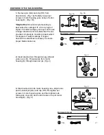
3.

 Use the fan reverse switch, located on the switch 

housing, to optimize your fan for seasonal performance. 
(Fig. 3) A ceiling fan will allow you to raise your 
thermostat setting in summer and lower your thermostat 
setting in winter without feeling a difference in your 
comfort.

Note:

 Wait for fan to stop before moving the reverse 

switch.

      3A.

 In 

warmer

 weather, setting the reverse switch in  

          the 

DOWN

 position will result in downward airflow  

          creating a wind chill effect. (Fig. 3A)


3B.

 In 

cooler

 weather, setting the reverse switch in  

          the 

Up 

position will result in upward airflow that      

          can help move stagnant, hot air off the ceiling    
 

area. (Fig. 3B)

IMPORTANT

: Reverse switch must be set either 

completely


UP

 or 

completely


DOWN

 for fan to 

function. If the reverse switch is set in the 

middle


position (Fig. 3C), fan will not operate. 

FAN OPERATION

At least twice each year, lower canopy (B) to check downrod (A) assembly, and then tighten 
all screws on fan. Clean motor housing (E) with only a soft brush or lint-free cloth to avoid 
scratching the finish. Clean blades (I) with a lint-free cloth. You may occasionally apply a 
light coat of furniture polish to wood blades for added protection.

Important:

 Shut off main power supply before beginning any maintenance. Do not use 

water or a damp cloth to clean the ceiling fan.

CARE AND MAINTENANCE

Summary of Contents for CEDAR HILL

Page 1: ...14 MODEL E PEN44BCW5MC CEDAR HILL CEILING FAN espa ol p 20 Harbor Breeze is a registered trademark of LF LLC All Rights Reserved E206035 Federal regulations require all ceiling fans with light kits ma...

Page 2: ...dware Contants 5 Preparation 6 Initial Installation 6 7 Downrod Style Fan Mounting 8 9 Closemount Style Fan Mounting 9 10 Wiring 10 12 Final Installation 12 15 Fan Operation 15 16 Care and Maintenance...

Page 3: ...let box Most outlet boxes commonly used for the support of lighting fixtures are not acceptable for fan support and may need to be replaced Consult a qualified electrician if in doubt Secure the box d...

Page 4: ...pre attached to motor housing 1 G Glass Shade 1 H Blade Arm 5 I Blade 5 J Pull Chain Extension in hardware pack 2 K Light Kit Fitter 1 L Finial Plate pre attached to light kit fitter 1 M Finial pre a...

Page 5: ...ttached to motor screw in hardware pack Blade Washer in hardware pack 16 E3 Wire Connector in hardware pack 4 Canopy Mounting Screw 4 attached to mounting bracket Pin in downrod 1 Clip attached to pin...

Page 6: ...electrical Phillips pliers safety stepladder wire tape screwdriver glasses strippers Helpful Tools not included A C tester tape do it yourself wiring handbook light measure available at Lowe s wire c...

Page 7: ...sure open end of mounting bracket C is installed facing the higher point of the ceiling 5 Remove motor screws AA and lock washers CC from underside of motor and save for blade arm H attachment later...

Page 8: ...A HH GG D B D E GG HH Hardware Used Pin x 1 Clip x 1 1 Remove pin GG and clip HH from downrod A Fig 1A Partially loosen set screws in motor housing yoke at top of motor housing E Fig 1B Helpful Hint...

Page 9: ...align slot in ball with tab may result in serious injury or death Continue to Wiring instructions on page 10 Fig 6 Hanging Ball Slot 1 Remove canopy cover O from bottom of canopy B Fig 1 Note It may b...

Page 10: ...grounded and that a ground green or bare wire is present WARNING If house wires are different colors than referred to in the following steps stop immediately A professional electrician is recommended...

Page 11: ...BY WALL SWITCH WHITE BLACK BLACK WALL SWITCH GROUND GREEN BARE BLACK BLUE WHITE FROM FAN Fig 1B FAN 120 V Power FROM CEILING 1 Choose wiring diagram Fig 1A Fig 1B or Fig 1C that fits your situation an...

Page 12: ...idual wire connector EE down to the wire as shown in Fig 2 WARNING Make sure no bare wire or wire strands are visible after making connections Place green and white connections on opposite side of box...

Page 13: ...ng with star washers from switch housing and remove switch housing cap F Locate BLUE and WHITE wires in switch housing labeled FOR LIGHT and remove plastic from these two wires Fig 4 Continue with Ste...

Page 14: ...x Connections 7 To attach light kit fitter K to fan align holes in switch housing cap F with holes in switch housing Note Make sure to align gap on top edge of the switch housing cap F with the revers...

Page 15: ...ng pull chains to come through corresponding holes in glass shade G Push up gently on glass shade G Thread pull chains through corresponding holes in finial plate L and center pull chain through hole...

Page 16: ...sition will result in upward airflow that can help move stagnant hot air off the ceiling area Fig 3B IMPORTANT Reverse switch must be set either completely UP or completely DOWN for fan to function If...

Page 17: ...s I 3 Switch one blade I with a blade I from the opposite side 4 Fan not securely mounted 4 Turn power off Carefully loosen canopy B and verify that mounting bracket C is secure 5 Fan too close to vau...

Page 18: ...ny glass provided with this fan is not covered by the warranty Any replacement of defective parts for the ceiling fan must be reported within the first year from the date of purchase For the balance o...

Page 19: ...ease have the Model or Item of the fan available which can be found on page 1 The following parts are replaceable REPLACEMENT PARTS LIST Part Description A Downrod B Canopy C Mounting Bracket D Yoke C...

Page 20: ...ngase en contacto con nuestro departamento de servicio al cliente al 1 800 527 1292 de 8 30 a m a 5 00 p m hora central de lunes a viernes 20 El reglamento federal requiere que cualquier ventilador d...

Page 21: ...25 Instalaci n inicial 25 27 Estilo de montaje del ventilador con el v stago 27 28 Estilo de montaje del ventilador sin el v stago 29 30 Conexi n de los cables 30 32 Instalaci n final 32 35 Funcionam...

Page 22: ...e las cajas de salida que se usan com nmente para sostener aparatos de alumbrado no son aceptables para sostener ventiladores y es posible que sea necesario reemplazarla Consulte con un electricista c...

Page 23: ...ano a la cubierta Paleta Pieza Descripci n Cantidad B O N M L K J I H G F E D C A en paquete de art culos de ferreter a Cubierta del yugo Bombilla de base candelabro Decoraci n para la cubierta en paq...

Page 24: ...ta 16 en el paquete de art culos de ferreter a Conector para cable E3 4 en paquete de art culos de ferreter a Tornillo para montaje de la cubierta 4 sujetado al soporte de montaje Perno en el v stago...

Page 25: ...ctura del edificio para que pueda sostener el peso total del ventilador El no hacer sto puede resultar en graves da os o la muerte La estabilidad de la caja de salida es esencial para minimizar tambal...

Page 26: ...nillos para montaje de la cubierta FF en los agujeros con ranura en la cubierta B y quite los otros dos tornillos para montaje de la cubierta FF gu rdelos para uso m s adelante Saque el soporte de mon...

Page 27: ...elegido en el paso 2 en la p gina anterior Art culos de ferreter a que se usaron ESTILO DE MONTAJE DEL VENTILADOR CON EL VASTAGO 1 Quite la clavija GG y el sujetador HH del v stago A Fig 1A Parcialmen...

Page 28: ...les para facilitar la conexi n de cables Si usted elige cortar los cables principales se le sugiere hacerlo de la manera que sigue Toma los cables principales y aseg rese de que los haya jalado comple...

Page 29: ...de la cubierta B Fig 1 Nota Es posible que sea necesario usar el mango de un destornillador para quitar la decoraci n para la cubierta O dando golpecitos en la decoraci n para la cubierta O desde por...

Page 30: ...encionados en los siguientes pasos suspenda el trabajo inmediatamente Se recomienda que un electricista profesional determine la instalaci n el ctrica que se debe hacer 1 Escoja el diagrama de instala...

Page 31: ...120 V cables de corriente DEL TECHO NEGRO BLANCO NEGRO AZUL TIERRA VERDE PELADO BLANCO DEL VENTILADOR VERDE BLANCO VENTILADOR VERDE Fig 2 EE EE EE 1C VENTILADOR Y LUZ CONTROLADOS POR DOS INTERRUPTORES...

Page 32: ...un brazo para la paleta H a una paleta I Luego apriete cada tornillo para la paleta BB empezando con el de en medio Fig 2 Repita esto con las dem s paletas I DD BB Tornillo para la paleta x 15 4 76 mm...

Page 33: ...s tornillos junto con las arandelas de estrella de la caja del interruptor y quite la cubierta de la caja del interruptor F Localice los cables NEGRO y BLANCO en la caja del interruptor etiquetados FO...

Page 34: ...ja del interruptor Fig 6 Aseg rese de que las conexiones tipo molex est n bien sujetas 7 Para sujetar el conectador para el juego de luz K al ventilador alinee los agujeros en la cubierta de la caja d...

Page 35: ...hacia arriba delicadamente en la pantalla de vidrio G Pase las cadenas de encendido por los agujeros correspondientes en la placa del adorno con rosca L y la cadena de encendido de en medio por el agu...

Page 36: ...te que podr servir para mover el aire caliente acumulado en el techo Fig 3B IMPORTANTE Hay que mover el interruptor de reversa o completamente hacia ARRIBA o completamente hacia ABAJO para que funcion...

Page 37: ...te al usar el ventilador a velocidad media o alta Tambaleo excesivo 1 Las paletas I est n flojas 1 Apriete todos los tornillos para las paletas BB 2 No se instalaron correctamente 2 Instale los brazos...

Page 38: ...ventilador est apagado de pared para el ventilador est prendido 4 No se conectaron correctamente 4 Verifique que se conectaron los cables en la caja del interruptor bien los cables en la caja del inte...

Page 39: ...pos de condiciones clim ticas esta garant a no cubre ning n cambio en el acabado bronce ni por la oxidaci n marcas la decoloraci n la corrosi n ni el descascarillado del material Se conserva la bellez...

Page 40: ...ara el juego de luz L Placa para el adorno con rosca M Adorno con rosca O Decoraci n para la cubierta LISTA DE PIEZAS DE REPUESTO Para piezas de repuesto llame a nuestro departamento de servicio al cl...

Reviews: