15
FINAL INSTALLATION
1
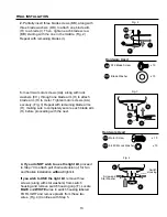
. The fan pull chain, located on the switch housing,
has four positions to control
fan
speed. One pull is
HIGH, two pulls is MEDIUM, three is LOW and four
turns the fan OFF. (Fig. 1)
2.
The pull chain in the middle is used to turn the
light
ON or OFF. (Fig. 2)
Fig. 2
Switch
Housing
Fig. 1
FAN OPERATION
Fig. 9
Fig. 10
9
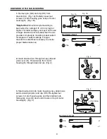
. Place white washer, that was removed on previous page
in Step 5, inside glass shade (G) over center hole. Align
center hole in the glass shade (G) with threaded rod in light
kit fitter (K), allowing pull chains to come through
corresponding holes in glass shade (G). Push up gently on
glass shade (G). Thread pull chains through corresponding
holes in finial plate (L) and center pull chain through hole in
finial (M). (
Align fan pull chain so that it does not rub
against light bulbs when fan is in operation.
) Tighten finial
(M) to secure glass shade (G) to light kit fitter (K). (Fig. 9)
Note
: Do not overtighten finial (M) as glass may crack or
break.
10
. The pull chain extensions (J) supplied in one of the
hardware packs or custom pull chain extensions (not
included) may be attached to fan and light pull chains.
(Fig. 10)
NOTE
: This fan is remote control adaptable (remote
control not included).
White
Washer
(For Fan)
(For Light)
K
L
G
M
J
G


