background image

-D2    -19

TURNING THE MACHINE ON

3_5b   M717

5-1b

 DANGER: To reduce the risk of electric shock.

Never leave the machine unattended when plugged in.
Always unplug this machine from the electrical outlet immediately after use and before per-
forming any maintenance on it.

 WARNING: To reduce the risk of burns, fire, electric shock, or injury to persons.

Do not unplug by pulling on cord. To unplug, grasp the plug, not the cord.

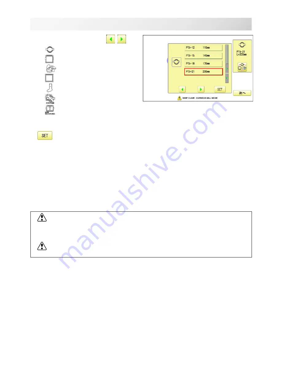
5. Select the desired frame with 


.

: Tubular round frame

: Tubular square frame


: Cap  and One-point frame.

: Border frame (for HCD2)

: Sock frame

: User-defined frame

: Non registered

6. Select desired type of frame and Press

.

The display returns to the view of Step 3.

To disconnect, switch the power switch to the
off position, then remove plug from outlet.

Summary of Contents for HCH

Page 1: ...CHN602 4 INSTRUCTION BOOK HCH Computerized Compact Single Head Embroidery Machine Original instructions...

Page 2: ......

Page 3: ...a 5 6 Selection of folders 5 9 How to select patterns from memory 5 A Erasing patterns from memory 5 B NEEDLE BAR SELECTION 5 E SEWING WITH TUBULAR FRAMES Installing and removing the frame base 6 1 Ho...

Page 4: ...ETTINGS 14 1 Scaling 14 2 Width adjustment 14 3 Angle 14 4 Repeat sewing 14 5 Auto origin 14 7 Offset 14 8 Frame out 14 D MACHINE SETTINGS 15 1 LOCK STITCHES 15 5 LETTER 16 1 QUEUE 17 1 Alter and Exec...

Page 5: ...amination repair electrical or mechanical adjust ment 4 Never operate the appliance with any air openings blocked Keep ventilation openings of the sewing machine and foot controller free from the accu...

Page 6: ...Injury risk on moving head s Keep hands away from the moving heads while the machine is running Laser beam Class 1 Do not stare into the beam ES HMF 5117 0 CAUTION Keep hands away from the moving hea...

Page 7: ...foam right and left 5 Take out the styrene foam lower front lower right and lower left Be careful not fall down the machine tilt the machine slightly when taking out the styrene form lower right and...

Page 8: ...list CD ROM Happy Link Software Instruction manual Embroidery frame Round Embroidery frame Square Thread stand Thread guide bracket Carriage Thread stand felt 9 pcs LAN cable USB cable Power line cord...

Page 9: ...d PTA 15 360 11 Needle DB X K5 10 pcs 12 Oiler 13 Sewing machine oil 14 CD ROM Happy Link 15 CD ROM Instruction manual Parts list 16 Instruction book How to open the CD ROM 17 LAN cable 18 Power line...

Page 10: ...ut the carriage and carriage arm together with screw M4 X 8 2 pcs 2 pins in the upper carriage arm will fit into holes on the lower carriage 6 Raise slowly the control box to the front then fix it wit...

Page 11: ...table when the machine is running If you have a problem Please use a stronger table for the machine 2_4 D607 2 5 SETTING UP THE MACHINE 350 mm 350 mm 720 mm 2 Please sit the machine level on the table...

Page 12: ...right side drawing 5 Please do not sit the machine near any kind of other electric equipment Examples Microwave or electric tool Has possible to wrong movement of the machine 6 Please keep away from...

Page 13: ...properly grounded Do not modify the plug provided with the product if it will not fit the outlet have a proper outlet installed by a qualified electrician This product is for use on a nominal 120 V ci...

Page 14: ...ing roller 11 Minor thread tension 12 Thread guide support 13 Thread guide 14 Upper rectifier 15 Thread stand pin 16 Thread stand felt 17 Thread stand 18 Control box 19 USB port Standard B receptacle...

Page 15: ...ad guide 2 Thread stand pin 3 Thread stand felt 4 Thread guide 5 Winder thread guide 6 Spindle 7 Lever CONTROL BOX 3 4 1 Display L C D 2 LAN port 3 Thread cut button 4 Start Stop button 5 3 6 1 16 7 5...

Page 16: ...roken or the Bobbin thread has run out Red Machine is running Orange Machine has detected an error An error number will be shown on the Display 24 1 5 USB port Standard A receptacle USB memory socket...

Page 17: ...can be controlled while embroidering Speed control Press the button to increase the machine sewing speed and the button to lower the machine speed is displayed on the LCD display Low speed operation...

Page 18: ...ou can raise or lower the presser foot Jump Off The machine can embroider Jump On Machine becomes jump and the machine doesn t embroider i Custom 22 1 You can place frequently used display and key ico...

Page 19: ...0 position When laser pointer is turned on moving head moves to needle no 0 position and radiates Locate Locate will restore the position of the frame to the last point before a power failure even if...

Page 20: ...eed turns gray and speed by the needle is applied to the speed set at Drive speed setting You can be set up taking the following steps 1 Press 2 Press 3 Change the setting on the needle number you wou...

Page 21: ...es that a frame out is occuring 3_A N525 3 8 DRIVE MODE Pointer Color change number sewn up to now Stitches of pattern Needle number and color Color change number Pointer indicates the position of act...

Page 22: ...efore removing the needle 1 Loosen the needle clamp screw slightly with the screw driver 2 Remove the needle 3 Insert a new needle into the needle clamp with push it up as far as it will go keeping th...

Page 23: ...7 0 6 0 5 0 0 1 0 8 0 3 1 0 0 1 0 3 1 0 0 1 2 1 0 8 3 1 5 8 0 4 6 3 0 7 0 6 0 0 1 0 8 0 5 1 0 3 1 4 1 0 9 5 1 5 9 6 1 0 0 1 6 3 0 3 0 6 0 5 0 8 0 6 0 6 1 0 5 1 7 1 5 0 1 8 1 0 1 1 0 3 4 2 0 5 0 4 0 6...

Page 24: ...iful embroidery Select backing type Choose the thickness and number of sheets by the type of material and embroidery condition Generally you should consider the following items Embroidery stitch quali...

Page 25: ...ess the limit lever as indicated by the arrow to start the winder The lever stops the winder automatically after the winding is complete 1 2 3 4 5 Ensure thread winds evenly on bobbin as shown Confirm...

Page 26: ...sert bobbin in case and draw thread up into slot in case 3 Draw thread under tension spring A and wind into guide coil B The bobbin should turn clockwise in the case when the thread is pulled Adjustin...

Page 27: ...re 1 Thread stand Set thread cone on the stand Small cones can also be used as shown 2 Thread guide Thread through the thread guide above each thread cone 3 Upper rectifier Continued next page 1 2 3 4...

Page 28: ...d upper threads one time around rotary tension disc clock wise 9 Upper thread guide 10 Lower thread guide 11 Lower rectifier 12 Thread adjusting spring 13 Take up lever 14 Thread guide plate lower 15...

Page 29: ...EMBROIDERY TERMS at the end of this instruction manual CAUTION To prevent accidents This will appear for items related to your safety CAUTION To avoid problems This will appear for items related to po...

Page 30: ...in sub menu 3 Press Illustration of the pattern selected will be dis played Right side of display shows the detail information of the current pattern data 4 Press The display returns to the view of St...

Page 31: ...r switch firmly so it will remain on 4 In case you do not need to change frame type Press After the moving head carriage and frame move the moving head and embroidery frame will return to the previous...

Page 32: ...reduce the risk of burns fire electric shock or injury to persons Do not unplug by pulling on cord To unplug grasp the plug not the cord 5 Select the desired frame with Tubular round frame Tubular sq...

Page 33: ...ss right left of to select the setting point and press up down of to select the number of year month and time 5 Press The date is fixed 6 Press to return to Menu mode Calendar and clock setting Settin...

Page 34: ...n g i s e d n i a g a n g i s e d w e s o t h s i w u o y f I n o m e t i d e p o o h y l w e n e s a e l p p o t s t r a t s s s e r p e n i h c a m n o t t u b p o t S e g n a h C u o y e s u a c e...

Page 35: ...as picture Clampfilter should be located close to machine Cable should be turned around clampfilter as picture 2 Please confirm filter is closed completely When the filter is removed please press latc...

Page 36: ...ect the LAN cable between the LAN port of the machine and the network of the PC Multiple and different type of machines can be connected to a PC which has Happy Link LAN software installed Please refe...

Page 37: ...lize the memory media with your PC please proceed with FAT or FAT32 format Handling note of memory media Do not bend drop disassemble charge or heat the memory media Keep away from humidity or direct...

Page 38: ...e machine If the Happy or Tajima pattern data has Barudan or ZSK data Tajima file DSB Barudan or DSZ ZSK The machine can read HAPPY and Tajima pattern data normally when Auto is selected at SETTING RA...

Page 39: ...ake room for the new patterns Once design is read Enable to read other pattern data If you wish to read another design continue to read other pattern data If you press the display will return to step...

Page 40: ...sired folder to choose or input pattern data Selected folder 1 When the machine is stopped press 2 Select PATTERN The pattern data of the selected folder will appear on the display 3 Select desired fo...

Page 41: ...hows the number name and details for the current pattern Number of stitches Number of Color change number Height Width 3 Select pattern data This pattern will be selected 5_A M620 How to select patter...

Page 42: ...desired pattern Mark will appear left of the pattern Make will be cleared by press it again Multiple pattern data can be selected Select all the pattern data Cancel pattern data erasing Erasing patter...

Page 43: ...ess 6 Push OK to delete The item will be deleted To delete other patterns repeat steps 4 to 6 Press Cancel to cancel the delete The display will return to step 2 Delete pattern 2 Cancel OK Showing num...

Page 44: ...4 Select the needle number on all the color change numbers Press to return to Menu mode 5 E NEEDLE BAR SELECTION 5_E N401 For each color change in a given pattern the needle number loaded with the co...

Page 45: ...e frame to a desired position automatically and stop it after the machine finishes sewing of that color change number When you resume operation the frame has an automatic return to previous position a...

Page 46: ...3 Select or Tubular round frame Tubular square frame User defined frame 4 Select desired type of frame Installing and removing the frame base Please attach the frame base to the carriage when you wis...

Page 47: ...by press 7 Place the frame base on the carriage guide and tighten the knob bolt on the tubular arm holder completely Move the frame base right or left when it is hard to tighten the knob bolts 6_1b N4...

Page 48: ...Inner frame Cloth Backing Outer frame Please stretch the embroidery cloth in the directions of the arrow to smooth the cloth Do not stretch the elastic cloth too much Please smooth the embroidery clot...

Page 49: ...imate center position before inserting the tubular embroidering frame 2 Insert the embroidery frame Make sure that the holder pins are inserted into the positioning holes of the frame base on each sid...

Page 50: ...ou want to start embroidering without tracing 3 Press after the trace is completed The embroidering frame has moved to the first stitch point of the pattern 4 Press The embroidery will start 5 After e...

Page 51: ...roider a cap 1 Remove the set screw 2 pieces by offset driver and remove the Standard needle plate 2 Put the needle plate for cap on the bed and tighten with the set screw 3 When the machine is stoppe...

Page 52: ...revent accidents The needle will down Please keep your hands clear for your safety 8 Using a 3 mm hexagonal driver Please turn the main shaft and adjust it to the L point 10 Loosen a fixing screw for...

Page 53: ...tically 12 Press to select next Needle Repeat steps from 6 to 11 then adjust Pressure foot height of all needles 13 Press Please return to a standard needle plate for flat sewing when you do not use c...

Page 54: ...he power switch 3 Hold the arc guide by hand and the rail bracket has to be faced downward then install into the bed as showing picture When you hold the cap drive frame assembly be sure to hold the a...

Page 55: ...wn at right 5 Move the cap drive frame in the direction of the arrow adjust right and left mount base to carriage arm and fix them by knob bolts 6 Fix the rail bracket to fixing base by knob bolts You...

Page 56: ...e 7 Turn on the power switch Selected frame is indicated 8 In case required Cap frame is already selected please jump to operation no 10 In case selected frame type is not same as your requirement Pre...

Page 57: ...the cap to adjust clamp tension At this moment the hook should open and close without feeling too tight For adjustment proceed to procedure 5 below Use the wing nuts for adjustment Fig 3 If the hook...

Page 58: ...sweatband Cover the cap stretcher with the sweat band so that the edge of the sweatband contacts the flange of the cap frame Please place one or two sheets of non woven fabric backing of standard thic...

Page 59: ...push the holder lever in the 2 places shown and place the cap frame on so that the center guide of the drive frame assem bly fits into the cap frame notch Confirm that the frame is firmly seated on th...

Page 60: ...Adjust the length of the cap grip to suit the thickness of the fabric At this mo ment hook should open and close without feeling heavy For the adjustment follow the next page Hooping caps item 1 to 5...

Page 61: ...eep open to the left 4 Take the front half of the sweatband out of the cap and cover the cap stretcher with the sweatband Cover the cap stretcher with the sweatband so that the edge of the sweatband c...

Page 62: ...ter guide of the drive frame assembly gets in the upper cap holder frame Confirm that the cap holder frame is firmly attached to the cap drive frame assembly without any gaps If there is a gap between...

Page 63: ...e the frame to the original point of pattern data by 2 Press After the moving head moves to the left end the laser pointerwill turn on The actual embroidery area will be restricted by the design and s...

Page 64: ...roidery will start 5 After finishing your design the display will show End and the machine will stop The embroidery frame will return to the original point automatically if the auto origin function ha...

Page 65: ...hole of the pressure foot pull it out slowly toward the front 2 Adjust the Minor thread tension by the first tension knob and then the second Thread tension knob According to the type of upper thread...

Page 66: ...suming sewing Even if you need to turn off the machine in the middle of embroidering you will be able to resume sewing from the stop point after turning on the machine back on If you leave the machine...

Page 67: ...p position 5 Press the The needle will go down and trim the thread 6 Press the After the carriage and frame move slightly the embroidery frame will return to the previous position automatically 7 Pres...

Page 68: ...ting point Origin The frame returns to the origin point beginning position of design 1 Press and press The frame will move to the origin point and the pattern data will return to the start point Top w...

Page 69: ...2 Press The pattern data will return to the start point Top will be shown on the display 3 Press Placing the design in the center of the selected embroidery frame Center Move embroidery frame position...

Page 70: ...SETTING 3 Press 4 Press to select conversion of position required The setting is fixed Normal Mirror reverse 0 90 180 270 0 90 180 270 Normal angle Normal Setting example Mirror reverse 90 With the s...

Page 71: ...ay from the frame Stitch 1 Press Frame forward 2 Press 3 Input the stitich number and press The frame will move to the selected stitch number position Pointer shows you the current position of the fra...

Page 72: ...ress 3 Input the color change number and press The frame moves to the selected color position Pointer shows you the current position of the frame CAUTION To prevent accidents The frame moves quickly K...

Page 73: ...ase line Align base line at the center of width of pattern Align pattern at left side of base line Align pattern with vertical base line Align pattern top of base line Align pattern at the center of b...

Page 74: ...s lWhen laser pointer is not installed press to lower pressure foot and instructing position is identified easily 4 Select alignment method Select in this case 5 Move frame with and align the pointer...

Page 75: ...8 Press Enter movement of arrow from base line edge of pocket to pattern Leave 0 0 when pattern is aligned to the center of base line width of pocket 9 Press 10 Press Angle and position of embroidery...

Page 76: ...can specify sewing position at specified pattern data number and specified number of stitch or color change number by entering the specified information Change Color position 9 7 This moves the frame...

Page 77: ...be moved a specified piece number 1 Press Frame forward 2 Press 3 Input the number and press The frame and pointer will move to the specified piece number CAUTION To prevent accidents The frame moves...

Page 78: ...ve frame When you use LOCATE keep clear of the frame and table It is dangerous as the frame could make sudden movements Never use locate with the needle bar and presser foot lowered as they could hit...

Page 79: ...ation Upper right indication of will be shown 3 8 3 Move the frame to the original point with the If the frame is located at the origin point proceed to Step 3 4 Press 5 Press The origin point is regi...

Page 80: ...right indication of will be shown 3 8 3 Press 4 press The frame will return to the origin point you registered and the display will return to Drive mode 9 F LOCATE 17_3 M401 Return In case of power fa...

Page 81: ...1 of free memory is equivalent to about 400 000 stitches If there are more stitches than remaining space you may need to delete some designs to make room for the new patterns 14_1 M525 Join Joining 2...

Page 82: ...ss The pattern data selected to be joined is joined next to the pattern data previously read in the machine as one pattern data and the screen returns to Menu screen Pattern name is registered as the...

Page 83: ...Combine jump No Yes Allows you to combine multiple consecutive jump stitches when reading pattern data if desired It combines them into jump stitches of the maximum 12 7mm and reads the pattern with...

Page 84: ...reload The data may only be HAPPY format TAP 9 Trace type You can compare the design size and design position to the embroidery frame before you start sewing The embroidery frame will move around the...

Page 85: ...0 Press to return to Menu mode 1 When the machine is stopped press 2 Select OPTION 3 Select 4 Select desired setting item and change the setting You can move to next page by pressing Press all setting...

Page 86: ...N 3 Press from right submenu 4 Select desired pattern Mark will appear right of the pattern Make will be cleared by press it again Multiple pattern data can be selected Locking pattern data Locking pa...

Page 87: ...D2 69 11 1b PATTERNS IN MEMORY 5_B M201 5 Press Repeat steps 3 and 5 to unlock Press to return to Menu mode...

Page 88: ...of the pattern data in the machine memory 14 5 1 When the machine is stopped press 2 Select PATTERN 3 Select desired pattern Maximum embroidery area of pattern Outline of pattern 4 Press and select o...

Page 89: ...H701 Export You can write out of machine memory to a memory media 1 When the machine is stopped press 2 Select PATTERN 3 Select desired pattern 4 Press from right submenu 5 Press from right submenu Th...

Page 90: ...n Choose the column with Then select each digit in the existing name Select word and press The pattern data will be written The maximum number of characters in a design name is eight letters or number...

Page 91: ...ect PATTERN 3 Select desired pattern 4 Press from right submenu 5 Choose the column with Then select each digit in the existing name Select word The maximum number of characters in a design name is ei...

Page 92: ...D2 74 6 Press The pattern name will be changed 11 5b PATTERNS IN MEMORY 11_5 M401 Press to return to Menu mode...

Page 93: ...pying of the pattern data stored in the machine memory is available Copied pattern data 1 When the machine is stopped press 2 Select PATTERN 3 Select desired pattern 4 Press from right submenu Copy of...

Page 94: ...6 11 7 PATTERNS IN MEMORY Moving pattern data Export pattern data into the other folder 1 When the machine is stopped press 2 Select PATTERN 3 Press from right submenu 4 Press from right submenu 11_8...

Page 95: ...desired pattern Mark will appear left of the pattern Make will be cleared by press it again Multiple pattern data can be selected Cancel pattern data moving 5 Press 6 Select the importing folder The...

Page 96: ...D2 78 11 9 PATTERNS IN MEMORY 11_9 M401 Renaming folders Rename folder in memory 1 When the machine is stopped press 2 Select PATTERN 3 Press from right submenu 4 Press from right submenu...

Page 97: ...h Then select each digit in the existing name Select word The maximum number of characters in a design name is 12 letters or numbers Uppercase and lowercase letter are switched All the letters are del...

Page 98: ...ate the pattern data in the displayed folder 1 When the machine is stopped press 2 Select PATTERN 3 Press from right submenu 4 Press from right submenu To sort in order of loading To sort in order of...

Page 99: ...D2 81 Press to return to Menu mode 11 Ab PATTERNS IN MEMORY 11_Ab M401 5 Select sorting method Sort will be carry out...

Page 100: ...heck construction of stitch design Press to return to Menu mode 1 When the machine is stopped press 2 Select PATTERN 3 Select desired pattern 4 Press from right submenu 5 Press from right submenu Thre...

Page 101: ...attern data can be moved to other folder and or deleted like monogramming data made on LETTER screen and other pattern data imported from outside of machine 11 7 5 B You can retrieve the pattern data...

Page 102: ...at color change number and then stops displaying the following message Auto setting Changes all designated needle numbers at once Thread color This sets the background color or color assigned to each...

Page 103: ...dle number to be changed 12 2 NEEDLE BAR SELECTION 13_2 N401 Needle number to be changed Auto setting This changes all designated needle numbers at once For example if you want to change all needles n...

Page 104: ...J 34 12 3 NEEDLE BAR SELECTION 13_2 N401 The needle number has been changed from 3 to5 6 Press Setting is cancelled Preview screen is displayed 7 Press The setting is fixed Press to return to Menu mod...

Page 105: ...ach needle bar to be shown in the display This is useful to help confirm the correct color setup of a pattern 128 colors are available You will find difficulty to see the pattern if you set same color...

Page 106: ...cloth back ground color 5 Select the color to be changed at the pal ette You can select the color with Current color will be shown 6 Press 7 Press The setting is fixed Preview screen is displayed curr...

Page 107: ...2 6 NEEDLE BAR SELECTION 13_5 N401 Color change data registration You can import and apply color change data from saved patterns Including color change stops to the current pattern This function lets...

Page 108: ...wn in the preview display 12 7 NEEDLE BAR SELECTION 13_6 M401 Color change data read You can export the registered color change data to other patterns If the pattern receiving the imported color chang...

Page 109: ...of group multiple number Machine display warning 12 8 NEEDLE BAR SELECTION 13_7 M401 Repetition of color group setting If your design has repetition of the group of the same color sequence only set f...

Page 110: ...ks whether or not the pattern fits the embroidery area of the frame you are going to use before starting the operation This is not a safety device that will prevent crashes if pattern size is too larg...

Page 111: ...ered 20 L 3 Select type of frame Change the type of frame Frame selection Selecting a frame The embroidery area for each registered frame is set to the inside of the frame edge to allow for pressure f...

Page 112: ...he embroidery area appear in red 5 Confirm that Top appears in the display and go to step 7 If this does not appear go to step 6 6 Press Top Upper right indication of will be shown 7 By position of de...

Page 113: ...he embroidery area can be adjusted for a variety of caps Fig 1 Embroidery area Embroidery area Side wise Fig 1 Embroidery area Lengthwise 1 When the machine is stopped press 2 Select FRAME 3 Select Ca...

Page 114: ...S2 36 13 5 FRAME CONFIRMATION 20_5 N101 6 Press 7 Press 8 Select the number Enter the width of the cap Size Y 40 67mm 9 Press 10 Press The setting is fixed...

Page 115: ...D2 133 13 6 FRAME CONFIRMATION 20_5 N101 11 Press Press to return to Drive mode...

Page 116: ...e of the frame edge for pressure foot clearance Fig 1 2 The embroidery area of each registered frame is set to the inside of the frame edge for pressure foot clearance Fig 1 2 When you use square fram...

Page 117: ...Press 8 Press to select the hoop Class Round frame Square frame 9 Press Select or you wish to change square frame size 10 Select the number Input number for size of embroidery area 11 Press Case for...

Page 118: ...D2 136 13 9 FRAME CONFIRMATION 20_9 M401 12 Press The date is fixed 13 Press Case for selected round frame Case for selected square frame Press to return to Drive mode...

Page 119: ...entered data You can entry the data up to 15 different size of custom frames You need to prepare custom frame size data for entry the size to your machine 13 B The embroidery area for each registered...

Page 120: ...t length from point from No L00 till L90 total 10 points size using between the each size data If your frame shape is Round the every 10 points length frame size data should be same If you select Type...

Page 121: ...the frame size data to machine usable memory media and read the data by embroidery machine 13 D Example of making the frame size data Sample for each teaching method 20_C N525 Ex Round frame Type 1 N...

Page 122: ...D2 140 13 D FRAME CONFIRMATION 20_D M717 Reading frame data 1 When the machine is stopped press 2 Select FRAME 3 Select User defined frames 4 Press You can choose any frame options 5 Press t...

Page 123: ...e data CCLAGOB txt The frame data has been read 8 Move embroidery frame to frame center point by 9 Press Memorized frame center point coordinate to the machine 10 Press 13 E FRAME CONFIRMATION 20_E N5...

Page 124: ...M717 1 When the machine is stopped press 2 Select FRAME 3 Select User defined frames 4 Press You can choose any frame options 5 Press t How to delete the resisted user defined frames 6 20 Delete resi...

Page 125: ...D2 143 13 G FRAME CONFIRMATION 20_I M717 6 Select desired User defined frames 7 Press The user defined frames will be deleted 8 Press Press to return to Drive mode...

Page 126: ...frame center point When you set your frame and use machine function of Frame move and Center 3 5 If your frame is not center please practice following steps for center setting again 1 When the machine...

Page 127: ...efined frames 7 Press 8 Press 9 Move embroidery frame to frame center point by 10 Press Memorized frame center point coordinate to the machine 11 Press Press to return to Drive mode CAUTION To prevent...

Page 128: ...dinates of frame position at the time of turning machine on Please select Non Registered Frame when you need use special frame which can hit pressure foot or other machine parts by movement of carriag...

Page 129: ...X and Y directions as set by the user Offset Sets the start point of the frame in the selected pattern Frame out Inserts a frame out command in the selected pattern Various settings are executed in a...

Page 130: ...1 When the machine is stopped press 2 Select SETTING 3 Select Scaling X or Scaling Y 4 Select the number Changing is cancelled Numbers are deleted 5 Press The setting is fixed Start point of pattern...

Page 131: ...is a case that error occurs at end point In such a case please return setting figure of stitch width to 0 0 Setting example 1 When the machine is stopped press 2 Select SETTING 3 Select Width adjustme...

Page 132: ...clockwise Setting example 1 When the machine is stopped press 2 Select SETTING 3 Select Angle 4 Select the number Changing is cancelled Numbers are deleted 5 Press The setting is fixed 30 Normal Start...

Page 133: ...n when you perform repeat When plus number is input the machine makes repeat toward right In case of minus number toward left Space Y 999 9 999 9 mm 0 This sets length wise distance between start poin...

Page 134: ...and select the number Changing is cancelled Numbers are deleted 4 Press The setting is fixed 5 Set necessary item by performing procedure no 3 to no 4 Set all the necessary items 14 6 PATTERN SETTINGS...

Page 135: ...turns to the start point Setting example 1 When the machine is stopped press 2 Select SETTING and select Offset 3 Press Auto origin and select ON or OFF The setting is fixed Start point of pattern End...

Page 136: ...ame to a place where it will be easier to handle when you will need to change hoops for example Direct input You can move the offset point manually and save the position with Teaching input Preset The...

Page 137: ...fset 3 Select X axis distance or Y axis distance and select the number Changing is cancelled Numbers are deleted 4 Press The setting is fixed 14 9 PATTERN SETTINGS 12_9 M717 Offset point Sidewise move...

Page 138: ...ffset point and press The setting is fixed Setting is unset 14 A PATTERN SETTINGS 12_A M717 Preset There are 9 preset points that can be used for offsets around the or in the center of the pattern Off...

Page 139: ...Offset 3 Select 4 Press 5 Move the frame to the pattern start point Setting is cancelled 6 Press The setting is fixed 14 B PATTERN SETTINGS 12_B M717 Sidewise move distance Lengthwise move distance O...

Page 140: ...6 14 C PATTERN SETTINGS 12_C M717 Complete Offset point Pattern data may be shown Setting is returned to the default To return to Menu mode 7 Move the frame to the offset point 8 Press The setting is...

Page 141: ...h original point as pivot Fig 1 In case offset is set the move distance is input with offset point as pivot Fig 2 You can set number of stitches or Color change number to make frame out in plural but...

Page 142: ...setting is fixed 14 E PATTERN SETTINGS 12_F M419 Teaching input Move the frame and the position will be saved as the frame out Frame out point Original point Start point of pattern Last position of C...

Page 143: ...Select SETTING and select Frame out 3 Select X axis distance or Y axis distance and select the number Changing is cancelled Numbers are deleted 4 Press The setting is fixed 14 F PATTERN SETTINGS 12_G...

Page 144: ...o f e b s t u c d a e r h t s t e s s i h T a t a d p m u j y t p m e n o m i r t s e o D a t a d p m u j y t p m e n o m i r t t o n s e o D s y a w l a G H C 0 1 t u c s e Y o N e g n a h c r o l o...

Page 145: ...t c n u f e z i s p u t e s e h t h t i w d e d n e t x e s i a e r a y r e d i o r b m e e h T d e d n e t x e t o n s i a e r a y r e d i o r b m e e h T t u o e m a r F 0 2 n o i t i s o p 0 0 0 1...

Page 146: ...Follow the steps 1 3 on the previous page and the display shows machine setting page 2 Press 3 Change the setting on the needle number you would like to change with Press when returning the setting on...

Page 147: ...ty of thread break detection needle by needle You can be set up taking the following steps 1 Follow the steps 1 3 on the page 15 2 and the display shows machine setting page 2 Press 3 Change the setti...

Page 148: ...TING ITEM 1 Cut Lock stitch is selected 3 Cut Lock Count 1 2 3 Set number of lock stitch when ON or AUTO on SETTING ITEM 1 Cut Lock stitch is selected 4 STR Lock stitch Add Lock stitch when the machin...

Page 149: ...aseline s width and height Press after setting is firmed Arch downward Cap line is formed a round arch in a downward direction Change settings of capline s width and depth Press after setting is firme...

Page 150: ...to lowercase The screen is switched to symbol The screen returns to menu Selected letter or number is deleted The cursor moves left and right Except for the space between letters space is eliminated 4...

Page 151: ...he right submenu 16 1 Initial layout method is horizontal straight line Line Length When layout method is horizontal you can change line length For other layout method than horizontal line length is n...

Page 152: ...enter of monogramming data Start point is the center of baseline or capline for arch and circle layout Create You can create embroidery data from the letter settings 11 Press The new pattern data will...

Page 153: ...ng screen 2 Select on space between letters you would like to change 3 Enter value 4 Press When you would like to make the same value on all the space at the same time select and enter value of the sp...

Page 154: ...tting of space can switched by pressing and Press The settings are firmed Letter setting screen Color change setting is made Color change between letters Color change can be made between letters When...

Page 155: ...at the end point of the last pattern Setting example Alter and Execution This registers Queued patterns in order and executes Needle bar selection and Pattern settings Needle bar selection and Pattern...

Page 156: ...ttern and press The selected pattern is shown to the left If you select other memory pattern data continu ously repeat step 4 19_2 M401 Alter and Execution This allows you to sew any combination of de...

Page 157: ...ttern selected will be dis played In case you do not need to check combined design please go to step no 7 6 Press 7 Press 8 Press 9 Press The machine will start a Queue embroidery with Queue operation...

Page 158: ...w for setting Needle bar selection 5 E Pattern settings 14 1 19_4 M401 Needle bar selection and Pattern settings Needle bar selection and Pattern Settings for patterns selected to QUEUE operation can...

Page 159: ...D2 125 19_4b M401 6 After setting press For setting of Needle Bar Selection NEEDLE and Pattern Setting SETTING to other design please do steps no 3 7 Press to return to Menu mode 17 5 QUEUE...

Page 160: ...er of the setting No Registration is deleted 4 Press QUEUE setting is registered as setting No 2 19_5 M401 Registration of QUEUE setting Up to 10 QUEUE settings can be registered Once you register QUE...

Page 161: ...7 7 QUEUE 19_6 M401 Read QUEUE setting Read registered QUEUE setting 1 When the machine is stopped press 2 Select QUEUE 3 Select 4 Select number and press QUEUE setting is selected Press to return to...

Page 162: ...ress right left of to select the setting point and press up down of to select the number 5 Press 18 1 OTHER SETTINGS Create network Set this menu when you use Network cable to connect PC and machine s...

Page 163: ...D2 151 6 Press 7 Press 8 Press The machine will be rebooted The setting is fixed 18 2 OTHER SETTINGS 22_1 M201...

Page 164: ...d press 2 Select OTHER 3 Press 4 Confirm version number Press to return to MENU screen The display returns to MENU When updating insert USB memory includ ing update file into the controller and press...

Page 165: ...GS 22_3a MA05 5 Press Update is starts Do not turn on power during updating The machine will reboot once update is com plete 6 Press The display will return to Drive mode Install_HAPPY_ version In pre...

Page 166: ...hange the language displayed on control box 22_3 M620 Press to return to Drive mode 1 When the machine is stopped press 2 Select OTHER 3 Press 4 Select the Language by 5 Press The language has been ch...

Page 167: ...tion of each icon and you cannot operate please adjust the screen as follows 22_3 M401 1 2 3 4 5 1 When the machine is stopped press 2 Select OTHER 3 Press 4 Press Prepare built in stylus 5 Press the...

Page 168: ...ETTINGS 22_3 M620 7 Press the screen with a finger any location is okay After this operation you can press the screen with a finger Adjustment is complete and the screen returns to Menu mode Press to...

Page 169: ...on Machine movement Change jump Change the needle bar s movement JUMP Needle Jump DRIVE Needle Drive Upper shaft turns Upper shaft turns clockwise and counterclockwise When release button upper shaft...

Page 170: ...moves quickly Keep hands away from the machine One equipment was not standby position ma chine show following message when you press key C point Upper shaft is not at C point Cut blade Thread cut bla...

Page 171: ...record Maximum memory is up to 10 If the record exceeds over 10 the new record will be added to the latest 9 records 3 In order to exit the mode proceed to the step 4 If you want to delete the record...

Page 172: ...t desired item 4 You can move to next page by pressing 5 Press You will return to the guide menu The GUIDE offers tips and step by step help for embroidering with the machine In each stage of embroide...

Page 173: ...en in numerical order when the machine is stopped and is not in operation for a certain amount of time Screen saver is cancelled when any place on the touch screen is touched If the setting time of di...

Page 174: ...Press 4 Select the direction 5 Press The setting is fixed and display returns to MENU 21 2 SCREEN SAVER 22_8 M620 Slide direction Set the slide direction of the screen saver image switched to the nex...

Page 175: ...e file Press the image file name you would like to add on the screen Ex The new image is added in the 006 5 Press The setting is fixed and display returns to MENU 21 3 SCREEN SAVER 22_9 M620 Change an...

Page 176: ...d and display returns to MENU 21 4 SCREEN SAVER 22_A M620 Initialization of registered images in the machine Screen saver images to set current status to initial status factory setting Original images...

Page 177: ...ng specifications by using your image editing software Save the image s in USB flash memory 800 pixels 480 pixels Pixelsof Image file File format BMP format Ex bmp Pixels 800 x 480 is recommended 1600...

Page 178: ...embroidery frame to the center auto matically Frame out 3 5 Move frame to the front position which was set before Original point return 3 5 This returns the frame to pattern origin point Origin regist...

Page 179: ...changing to other display or key icon s When you select the desired display or key repeat steps 3 and 4 Selected i CUSTOM is deleted Setting is returned to the default 5 Press The setting is fixed and...

Page 180: ...t i t s 0 0 0 0 0 0 0 4 t u o b A n r e t t a p d e r e t s i g e R t a p 0 5 2 1 Actual embroidery area will be restricted in accordance with inner frame size 2 Actual embroidery area will be restri...

Page 181: ...hook clean Use the included brush for cleaning the hook CAUTION To prevent accidents When taking care of the machine be sure to remove the plug Cleaning the thread cutting knife If the thread cutting...

Page 182: ...ste thread and dust from the knife assembly and surrounding area 6 Press Moving knife returns to the original position 23 3 MAINTENANCE 23_3 N401 CAUTION To prevent accidents The thread cutting knife...

Page 183: ...i t i n u n o i t c e l e s r a b e l d e e n r o y l t c e r r o c h t i w e l b u o r T n o i t i s o p p o t s s t i f f o d r a o b t i u c r i c g n i t c e t e d n o i t i s o p w o l e b s n o...

Page 184: ...a t a d n r e t t a p d a e R 4 5 8 0 1 d a e r r e p o r p m I s a h r o r r e a t a d n r e t t a p g n i d a e r e l i h W g n i s s e c o r p l a n r e t n i n i d e r r u c c o t r a t s e h t m...

Page 185: ...c t i w s t i m i L F F O w o l e b e l p m a x e e h t w o l l o f e s a e l P t u c y l l a u t c a s a w d a e r h t r e h t e h w k c e h C 1 d a e r h t t u c t o n f I e f i n k g n i t t u c d...

Page 186: ...and the display shows drive mode What to do for error E 020 E 026 1 Press 2 Select Manual The Error status is cleared and the display shows drive mode 3 Refer to the page in the section ERRORS AND WHA...

Page 187: ...en Stop position of main shaft is out of place error E 050 1 Press 2 Select Manual The error status is released and the display shows drive mode 3 Remove the cap over the small hole in the rear of the...

Page 188: ...SJ 89 24 5 ERRORS AND WHAT TO DO 24_6 N525 1 Press 2 Select Auto The display returns to the drive mode What to do for Thread cut knife is not at the stop position error E 190 E 190 Cut blade OK...

Page 189: ...h hook is off its position error E 193 1 Press 2 Select Manual The Error status is cleared and the display shows drive mode 3 Refer to the page in the section ERRORS AND WHAT TO DO and determine what...

Page 190: ...n performed all settings in the OPTION menu are lost Be sure to reset the OPTION menu after performing this function System initialize OK Cancel OK 1 When the machine is stopped press and Press 2 Pres...

Page 191: ...rease from slowest speed to maximum and then stop automatically and return to Drive mode If you cancel press the The display returns to MENU 25 2 INITIALIZING OF MACHINE SETTINGS 25_2 M201 Initializin...

Page 192: ...M y l t c e r r o c n i d e d a e r h t n i b b o B e l d e e n t n u l B t h g i t o o t n o i s n e t d a e r h T e n i h c a m d a e r h t e R n i b b o b e h t d a e r h t e R e l d e e n w e n t...

Page 193: ...he frame position where the machine embroiders the pattern from the beginning is automatically registered as the original point Stitches This is the minimum unit within the pattern data There are diff...

Page 194: ...SJ 81 Those fonts are created by www i cliqq com 26 3 BUILT IN FONT LIST 26_3 N401...

Page 195: ...SJ 93 BUILT IN PATTERN includes clip art from Master clip created by H2soft Fax 81 422 28 5211 E mail support office4dc co jp 26 4 BUILT IN PATTERN LIST 26_4 N602...

Page 196: ...M510E HEAD OFFICE 3 3515 Tachiyagawa Yamagata city 990 2251 Japan Phone 81 23 686 2272 Fax 81 23 686 2243 TOKYO OFFICE 2 9 5 Taito Taito Ku Tokyo 110 0016 Japan Phone 81 3 3834 0711 Fax 81 3 3835 8917...

Reviews: