background image

installation & connection

18_

 installation & connection

POWERING AND NETWORKING

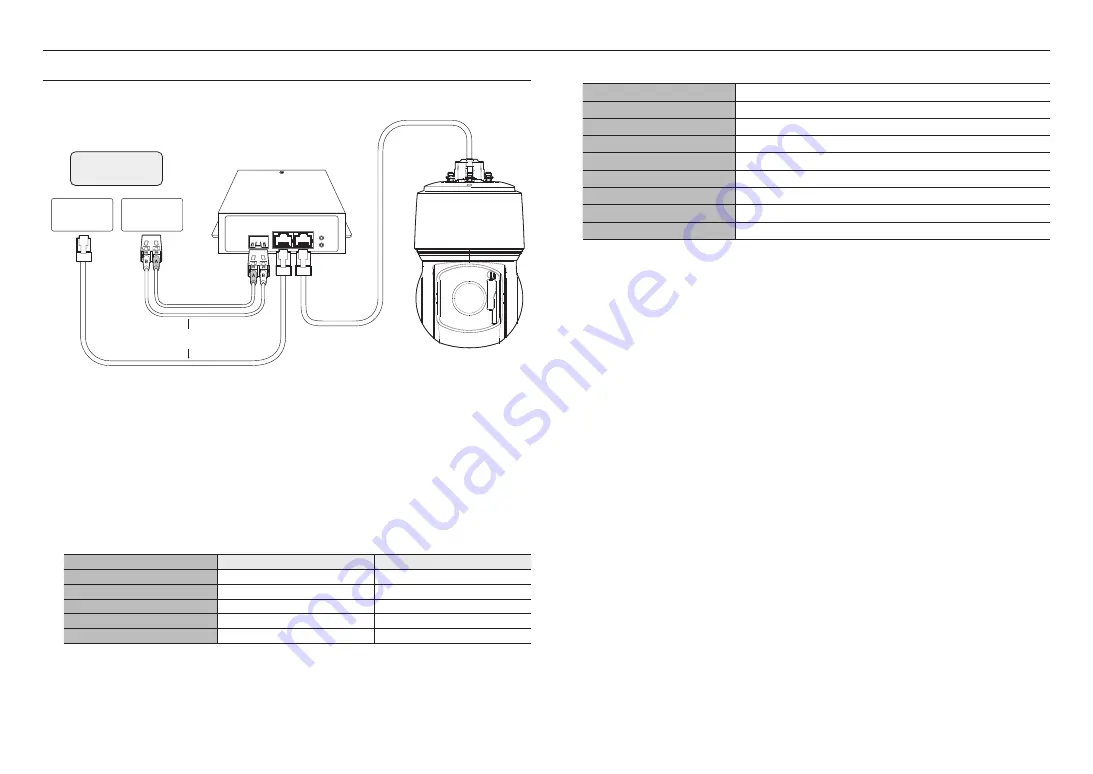
Connect the HPoE injector with the HPoE port  of the camera.

LAN

SFP

PoE

0Link

POWER

Switch

SFP module

SFP Port 

Switch

External internet

HPoE injector

OR


J


`

The product cannot be used at -40°C or below ambient temperature.


`

The product may not be defrosted depending on the installation area at -40°C.


`

After the product is left alone under a low temperature environment, it will take up to 2 hours to normally operate.


`

If the product is turned on after being exposed to -20°C or below environment for some time, reset the time.


`

Use the provided HPoE injector when connecting power and network.


`

Use only either one of network cable or fiber optic cable for connection.

Network Cable Specification

Item

Contents

Remark

Connector

RJ45 (10/100BASE-T)

Ethernet

10/100BASE-T

Cable

UTP Category 5e

Max Distance

100m

DC Resistance ≤ 0.125 Ω/m

HPoE Support

HPoE


M


`

Use an STP cable to increase the protection from thunderstroke damage.

SFP port Specification

Support SFP Voltage

3.3 V Typical

Support SFP Current

300 mA Max.

Support SFP Cage

Standard mini-SFP Cage(for 6.5 mm pitch SFP)

Support SFP Port Type

LC Type

Required SFP Speed

1250 Mbps(For 1000 Mbps Ethernet)

Required SFP’s BER(Bit Error Rate)

Max 10

-12

Transmission Method(Optical)

Mode Depends on SFP Module

Optical Mode(Long/Short Wave)

Mode Depends on SFP Module

Cable Insertion Loss(dB)

Mode Depends on SFP Module


J


`

The connection/disconnection of the SFP module must be made only after the HPoE injector is turned off.


`

A kink in the optical cable may disrupt the connection for communication.


`

Do not directly look at the optical cable. It can damage your eyes.

Summary of Contents for XNP-C9303RW

Page 1: ...NETWORK CAMERA User Manual XNP C9303RW XNP C8303RW XNP C6403RW...

Page 2: ...correctness of the contents in this document but no formal guarantee shall be provided Use of this document and the subsequent results shall be entirely on the user s own responsibility Hanwha Vision...

Page 3: ...y be damaged 18 Do not install the product in a place where chemical substances or oil mist exists or may be generated As edible oils such as soybean oil may damage or warp the product do not install...

Page 4: ...n surface Do not install on a surface where it is exposed to direct sunlight near heating equipment or heavy cold area Do not place this apparatus near conductive material Do not attempt to service th...

Page 5: ...alarm I O NETWORK CONNECTION AND SETUP 20 20 Connecting the Camera Directly to Local Area Networking 20 Connecting the Camera Directly to a DHCP Based DSL Cable Modem 21 Using Device Manager 21 Automa...

Page 6: ...b viewer depends on the performance of the user s CPU and GPU RECOMMENDED MICRO SD SDHC SDXC MEMORY CARD SPECIFICATIONS Recommended capacity 16GB to 1TB MLC type required Recommended Manufacturers San...

Page 7: ...ling apart from the hole Cable Bushing 1 Extra cable bushing for network cable installation NETWORK I O BOX SEPARATELY SOLD PRODUCT Appearance Item Name Description Model Name Network I O box External...

Page 8: ...can be opened using Torx drivers etc Inside Item Description a IR LED These infrared LED s are controlled by the illumination sensor b Lens Lens for the camera c Illumination Sensor Detects incoming...

Page 9: ...ber cap which allows a network cable to go through it b Safety wire hook Hang this hook on the safety wire of the mount when installing this product to prevent it from falling c HPoE port A port that...

Page 10: ...n Forcing assembly using non compliant tools may damage the product Inserting a Micro SD card 1 Unfasten two screws on the Micro SD card cover by turning them counterclockwise using the Torx screwdriv...

Page 11: ...ains data from the product the data may be lost or damaged Preparing Installing Camera Mount For installation guidelines for mounts refer to the installation manual that is enclosed with the mount M S...

Page 12: ...e installation is in progress may cause fire or damage the product 1 Hang the safety wire of the wall pole mount on the safety wire hook of the product Safety wire hook Safety wire 2 Connect the netwo...

Page 13: ...hook and click each side into place one at a time 5 After aligning the installation direction guides of the camera and wall pole mount push the main cover upward and turn it counterclockwise until it...

Page 14: ...to the network port 3 Plug the cable bushing of the network cable in the hole When plugging it in press the whole bushing area evenly so that it is properly plugged in J The length and width of the ca...

Page 15: ...guides of the hanging mount push the main cover upward and turn it counterclockwise until it is secured 6 Tightly fasten the 3 mounting screws on the top side of the mount TR30 Joined with official p...

Page 16: ...an official product mounts If you use hanging mount you can install the camera onto any mount other than the official product mount Hanging Mount SBP 156HMW Wall Mount SBP 300WMW Hanging Mount SBP 156...

Page 17: ...cleaning the window properly you can replace the rubber part 1 Lift up the wiper 2 Pull the wiper blade back 3 Remove the rubber part by pulling it back 4 Insert the rubber replacement in the joint g...

Page 18: ...etwork Cable Specification Item Contents Remark Connector RJ45 10 100BASE T Ethernet 10 100BASE T Cable UTP Category 5e Max Distance 100m DC Resistance 0 125 m HPoE Support HPoE M Use an STP cable to...

Page 19: ...ld Network Speaker Microphone SPM 4210 Alarm Warning lamp Sensor M For more information on the network I O box see the manual for the network I O box You can set the network I O box in Camera web view...

Page 20: ...e the IP address use the Device Manager For further details on Device Manager use refer to Using Device Manager Page 21 Local Network Switch Camera Camera Local PC INTERNET External Remote PC DDNS Ser...

Page 21: ...Port Used to access the camera using the Internet browser defaulted to 80 RTSP Port A port that controls real time streaming The initial value is 554 If using a Broadband Router IP Address Enter an a...

Page 22: ...yed click OK MANUALLY REGISTERING CAMERA If the camera cannot be found using search function the camera can be registered remotely by manually inserting IP information if the camera is connected to ex...

Page 23: ...ng setting is an example of setting CISCO IP router The settings may differ depending on the connected Broadband Router model For more information refer to the user manual of the applicable router Set...

Page 24: ...A THE INTERNET On a remote computer that is not in the Broadband Router s network cluster is not allowed users can access cameras within a Broadband Router s network by using the camera s DDNS URL 1 B...

Page 25: ...in support of the UPnP protocol 2 Click the camera name for search In the Windows operating system click the camera name searched from the network menu The login window is displayed Connecting via Bon...

Page 26: ...by using a memo pad or memorizing it LOGIN Whenever you access the camera the login window appears Enter the User ID and password to access the camera 1 Enter admin in the User name input box The admi...

Page 27: ...without formatting the default folder saved or used Confirm that you used recommended NAS equipment TROUBLESHOOTING PROBLEM SOLUTION No video is displayed when accessing the plug in free webviewer on...

Page 28: ...ury cadmium or lead above the reference levels in EC Directive 2006 66 If batteries are not properly disposed of these substances can cause harm to human health or the environment To protect natural r...

Page 29: ......

Reviews: