background image


10 - 20


Hanskamp AgroTech B.V. (the Netherlands) 

www.hanskamp.nl/en


Pipefeeder 

EN 

24VAC & 12

-

24VDC 

Adjusting the DC PipeFeeder anti-spill device 

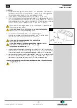
7.  The DC version of the PipeFeeder (anti-spill) should be correctly  

adjusted before this is put into service. Adjustment is performed 
as follows:  

 

Ensure that the PipeFeeder is full of feed than allow the  


motor to rotate once (give signal).  

 

For the settings of AC with DosPrint Pipefeeders, check the DosPrint man-
ual. (Art.nr. 1825) 


Please note! Make sure to first switch off the electric  
power to the control unit before the next step.  


 

Remove the lid from the PipeFeeder. Remove the motor plate by unscrew-
ing 4 bolts.  

 

Remove the motor with motor plate and connector from the shaft.  

 

Turn the star on top of the drive shaft. Make sure that the arrow on the star is 
level with the recess on top of the stainless steel pipe. 

 

Push the motor with motor plate and connector back onto the drive axis.  

Mount these by screwing the 4 bolts tight again.(pic.3) 

 

Fit the lid back onto the PipeFeeder.  

 

Switch the electronic power back on.  

 

Fill the PipeFeeder and allow to rotate once for control (give signal).  

 
This adjustment should be applied in both the milking stall feeding installation, in parlour, 
and in the feeding box, out of parlour.  
 
8. 

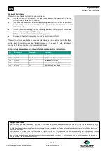
When installation is not completely correct the plastic part will be able to rotate 
freely with respect to the stainless steel tube. When the plastic part is rotated in 
case of the DC version the adjusting procedure should be followed again (step 7). 
In addition it must be ensured that after mounting or twisting of the plastic part, 
the motor is correctly placed onto the axis 


Important!


 

Only when the motor is correctly adjusted can Hanskamp Agro


Tech   guarantee that the PipeFeeder is Anti-spill.  

 

Make sure that all the wires are neatly concealed out of reach of 


animals. Otherwise hazardous situations can emerge.  

 

Before you run the PipeFeeder, always fit the lid which covers the  


motor carefully. Otherwise hazardous situations can emerge  


     (pic. 4). 

 
9.  The PipeFeeder has fully electrical operation. The motor drives the axis that turns a 

scoop mechanism at the bottom of the stainless steel pipe (Ø129 x 2mm). This mech-
anism delivers the feed. If a switch is used to control several dosing units at the same 
time, such asl on each side of the parlour (milking stall feeding), then several Pipe-
Feeder dosing units can be connected to a single feeding line. Please note the maxi-
mum permissible current, which is stated on the power supply (art.nr. 2812 or 2813 
PowerUnit), won’t be exceeded. 


Summary of Contents for PipeFeeder

Page 1: ...truction Article number 1847 Datum August 2014 Version 2 2 Translation of Original Instructions for use According to Annex 1 Chapter 1 7 4 Machine guideline 2006 42 EG Zelhem The Netherlands www hansk...

Page 2: ...faults in this manual The recommendations are meant to serve as guidelines All instructions pictures and specifications in this manual are based on the latest information that was available at the tim...

Page 3: ...vative PipeFeeder concentrate feeding system from Hanskamp which ensures pellets are fed precisely and silently The PipeFeeder features an ingenious anti spill system also developed by Hanskamp On ce...

Page 4: ...of your PipeFeeder YOU must make sure that you and anyone else who is going to operate maintain or work in the vicinity of the PipeFeeder knows all the related SAFETY information in this manual YOU a...

Page 5: ...of the electrical system and all parts of the PipeFeeder meet the local rules and regulations Replace any damaged electrical lines conduits switches and components imme diately Isolate the electrical...

Page 6: ...electrical power supply by taking plug out of the power point and secure the plug before you clean or do maintenance on the PipeFeeder Wear protective clothing and safety goggles when you do work on t...

Page 7: ...nskamp please consult the instal lation instruction no 1840 for connecting and adjusting the PCB See the annex for the order numbers and names of the various parts Transport and storage The PipeFeeder...

Page 8: ...ht position for the sticker Remove a small portion of the foil on the back Place the sticker on the surface and press a small portion of the self adhesive layer onto the surface Carefully remove the f...

Page 9: ...PipeFeeder This way air can run underneath the PipeFeeder 4 Use a well shielded electricity cable to connect the dosing unit See the annex on page 15 for the connection diagram for the various motors...

Page 10: ...milking stall feeding installation in parlour and in the feeding box out of parlour 8 When installation is not completely correct the plastic part will be able to rotate freely with respect to the sta...

Page 11: ...eeder cannot start unexpectedly Make sure there is no voltage on the installation To do this plug the power supply off at the control unit of the dosing motor 3 It is recommended to have repairs and m...

Page 12: ...nformation given in this publication is provided for information purposes only and does not constitute an offer for sale The products supplied may differ from those illustrated No part of this publica...

Page 13: ...fully complies with the provisions of the following di rective s Machine Directive 2006 42 EC and completely or partially meets the following essential requirements and that the rele vant technical do...

Page 14: ...ece between the motor and drive shaft could be broken Remove motor of rotor and reinsert note settings for anti spill pag 10 step 7 Constipation by for example wood or plastic Remove the PipeFeeder of...

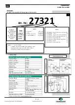
Page 15: ...24VDC 28 rpm Anti spill Solid State 5 DV 7 1663 24VDC 28 rpm OV 8 1001 24VDC 41 rpm Anti spill DV Example Art No 27321 A 1500mm normal blue PipeFeeder with SolidState motor HighSpeed version always m...

Page 16: ...anskamp nl en Pipefeeder EN 24VAC 12 24VDC Loose components It is possible to reorder loose components from your supplier for maintenance or for any other reason Please use the item numbers shown belo...

Page 17: ...94 Bottom plate AC 1 1895 Angled safety plate 1 1896 Bottom plate DC HighSpeed 1 1899 Sheet section of sealed compartment 1 1902 Wall mounting bracket 129 complete 2 1903 MDPE plastic T piece 45 with...

Page 18: ...18 20 Hanskamp AgroTech B V the Netherlands www hanskamp nl en Pipefeeder EN 24VAC 12 24VDC Installation dimensions Visit us on 10...

Page 19: ...19 20 Hanskamp AgroTech B V the Netherlands www hanskamp nl en Pipefeeder EN 24VAC 12 24VDC...

Page 20: ...20 Hanskamp AgroTech B V the Netherlands www hanskamp nl en Pipefeeder EN 24VAC 12 24VDC Hanskamp Arendsenweg 7 7021 PC Zelhem The Netherlands Tel 31 0 314 393 797 Fax 31 0 314 393 826 www hanskamp n...

Reviews: