Hanshen MP350 Series Operation Manual Download Page 41

41

Table16

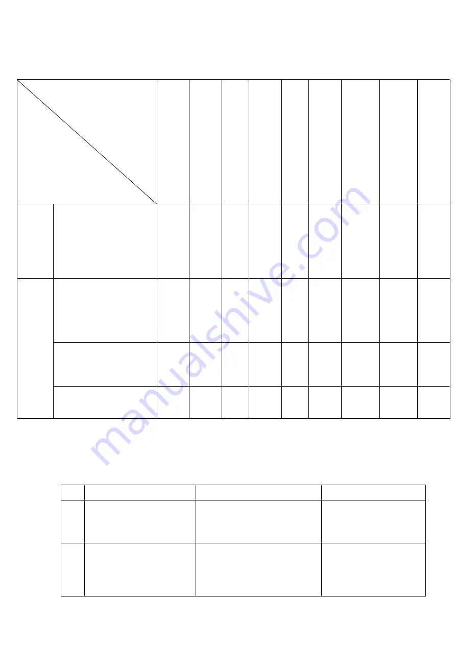
8.3 Common troubleshooting

Table 17

NO

Phenomenon

Reason

Method

1

After startup. Light is not

illuminated

1) on the back panel of the

automatic air switch is

damaged

2) power source fuse break

1

change it

2

change it

2

After connected to power,

Automatic air switch off

the power

1) automatic air switch failure

2) the damage of IGBT module

3) three-phase rectifier bridge

damage

4) welding machine control

replace

Abnormal

Overhaul parts

and repair items

Can not

ignite

the arc

Shield

gas can

not

flow

out

Does

not

send

wire

Igniting

the arc

hardly

Arc is

not

stable

Weld

edge

unclear

Adhesive

base

metal

and

welding

wire

Adhesive

welding

wire and

contact

tip

Appear

gas

hole

Wire

feeder

1) pressure regulating

handle too tight or too

loose

2 nozzle with powder

accumulated

3) the wire feed wheel

abrasion, jam

torch

1)welding torch cable

bending much

2) contact tip, wire feed

tube adaptability

3) wear, jams,

deformation, etc

contact tip, nozzle, the

nozzle joint loose

connector joint is not

good

Welding torch cable,

torch switch control cable

broken

Summary of Contents for MP350 Series

Page 1: ...Be sure that all installation operation maintenance and repair procedure are performed only by qualified individuals Read this operation manual completely before using this equipment Save this manual...

Page 2: ...P M E N T I N S T A L L A T I O N C O N N E C T I O N 1 0 5 F U N C T I O N I N T R O D U C T I O N 1 2 6 W E L D I N G O P E R A T I O N 2 2 7 W E L D I N G M A T E R I A L S E L E C T I O N 3 5 8 D...

Page 3: ...n box when wiring Do not touch the exposed live parts Do not touch the overheating parts produced by the current between the welding and the workpiece with bare hands or place parts of body or wet clo...

Page 4: ...urrounding areas through small crack and holes Take suitable measures here to ensure that there is no risk of injury Welding must never be performed on containers which still have gases fuels mineral...

Page 5: ...that are suitable for the application in question together with matching suitable accessories pressure regulator hoses fitting and hose clamp When opening the valve of a shielding gas cylinder always...

Page 6: ...al discharge of hot coolant before unplugging the connectors of coolant flow switch off the cooling unit first If need to use the machine under electricity environment only use it when the safety symb...

Page 7: ...d in industrial and workshop environments The manufacturer shall not be liable for any damage resulting from using of the machine in residential premises Likewise the manufacturer will accept no liabi...

Page 8: ...lloys and other non ferrous metal welding The constant pressure welding method can be used for carbon steel rich in argon and CO2 gas shielded welding Advantages 1 Fully digitally controlled system ac...

Page 9: ...urrent 25A 36A 4 Rated duty cycle 60 5 Range of rated output current adjusting 20 350A 20 500A 6 Range of rated output voltage adjusting 11 34V 11 40V 7 Output open circuit voltage 58V 68V 8 Efficienc...

Page 10: ...10 4 EQUIPMENT INSTALLATION CONNECTION 4 1Connection diagram for example melting pole welding...

Page 11: ...11 3 415V Fig 1 connection diagram...

Page 12: ...o health Do not inhale any fumes or noxious Clean up the oil spill on the workpiece Keep air circulation of welding site Welding station should be equipped with exhaust smoke and dust cleaning equipme...

Page 13: ...ion etc read instructions for operation manual of MP series welding machine panel 2 Cathode output connector Through the output cable to connect the welding workpieces gas metal arc welding 3 Control...

Page 14: ...ect the voltage transformer cooling fan and etc 9 Heating power fuse When the heating regulator short circuit occurs the fuse will blow to protect control transformer cooling fan and etc 10 Heating ou...

Page 15: ...light of adjusting knob When indicator light is on it means the knob can adjust the parameters 3 Selection key F2 Choose to operate the parameters of the project Arc length correction welding voltage...

Page 16: ...nt 10 The display screen on the right Display related parameters 11 The display screen on the left Display related parameters 12 indicator light of the arc force arc lamp When using pulse MIG MAG weld...

Page 17: ...ed 21 storage key Enter the settings menu or store parameters 22 indicator light of wire diameter When indicator light is on it means it can adjust wire diameter 23 selection key of wire diameter Sele...

Page 18: ...f welding method Table 5 welding method Welding methods Note P MIG Pulse welding MIG MAG Unified dc welding STICK Manual welding TIG Tungsten argon arc welding CAC A Carbon arc air gouging 5 4 Implici...

Page 19: ...to adjust to parameter values P05 P06 item are available for F2 key switch to display current percentage arc length offsets and can also use 1 to modify the parameter values Detailed operation referen...

Page 20: ...time 0 01 2 00s 0 01s 0 08s P02 Slow wire feeding speed 1 0 21 0 M min 0 1 M min 3 6 M min P03 time of Plenum ahead 0 1 10 0s 0 1s 0 20s P04 time of Stop lagging gas 0 1 10 0s 0 1s 1 0s P05 early spe...

Page 21: ...matic or fully automatic weld Invoking mode can improve the quality of welding technology for both This mode of operation has the memory function it can store and obtain as many as 100 different assig...

Page 22: ...successful storage At this time stored button 21 can be released 6 Gently press storage key 21 exit the storage condition Fig7 Storage program diagram 5 6 2 Invoking program After storage all operati...

Page 23: ...ting 6 2 Melting polar gas shielded welding installation commissioning and operation Reference figure 1 the equipment connection diagram gas welding molten 1 Connect the one end of the integrated cabl...

Page 24: ...sponding parameters in the database which greatly reduces the complexity of the welder operation Users only need to set the welding mode operation mode the type of material wire diameter and the curre...

Page 25: ...90 18 19 50 60 10 15 L 1 2 1 6 1 0 1 2 100 18 50 60 10 15 L 1 2 1 2 120 19 20 40 50 10 20 L 1 2 2 0 1 0 1 2 115 19 5 50 60 10 15 L 2 3 3 2 1 0 1 2 150 21 22 45 50 15 20 L 2 3 1 2 200 24 26 45 60 10 2...

Page 26: ...13 15 L 2 3 3 2 1 2 160 200 23 26 40 50 13 17 13 15 L 2 3 4 5 1 2 200 24 28 45 55 15 20 15 17 L 3 4 6 0 1 2 270 300 28 31 60 70 18 22 18 22 L 3 4 8 0 1 6 280 320 27 31 45 60 18 22 18 22 L 4 6 10 0 1 6...

Page 27: ...of this welding machine is a closed digital wire feeding machine with a fully digital raster feedback closed loop control function to ensure the accuracy and stability of wire feeding speed The wire...

Page 28: ...b to adjust the given current use V knob to adjust the given arc length Wire feeding mechanism with four wheel drive as shown in figure 11 Fig 11 Wire feeding mechanism diagram Gas tube interface Wire...

Page 29: ...ire 3 Type 3 is suitable for flux cored welding wire Use pressure handle to adjust wire feeder roller pressure keep welding wire into the catheter evenly and allow a little brake force when the wire c...

Page 30: ...rent adjustment Knob can adjust wire feeding speed Loosen the wire feeder button wire feeding stops Press gas detection button and open the valve do not start wire feeding machine and welding machine...

Page 31: ...stance and effect wire feeding instability Tighten the torch quick connectors in order to make sure there is no voltage drop on the surface of the contact Loosing contact lead to pressure drop which w...

Page 32: ...tube to move the wire feeding machine 2 When connecting the gas tube or when welding machine is not in use please close the cylinder valve 3 If use water cooling torch pure water must be used and kee...

Page 33: ...ilure 1 check communications wiring 2 replace the main control bo board E41 Wire feeder internal main board communications is abnormal 1 Communications wiring is loose or short line 2 The wire feeder...

Page 34: ...the signal line is disconnected 4 the main control board fault 1 Check the main circuit power device 2 restart power supply 3 check signal line 4 change board E18 Output voltage abnormal 1 voltage fe...

Page 35: ...ch and current curve Two step 1 press the torch switch start welding 2 Turn off switch stop welding Four step 1 press the torch switch start welding 2 turn off switch keep the welding state 3 press th...

Page 36: ...elding 1 press the torch switch began to welding set continuous spot welding time welding automatic stop 2 press the torch switch before set spot welding time to loosen the switch stop welding 7 WELDI...

Page 37: ...4047 stainless steel 0 8 1 0 1 2 1 6 304 308 309 316 Such as austenitic stainless steel welding wire 97 5 Ar 2 5 CO2 carbon steel E70 82 Ar 18 CO2 silicon bronze 1 2 1 6 HS211 100 Ar aluminum bronze 1...

Page 38: ...he welding machine be exposed to sunlight for long periods of time Don t work in strong sunlight Don t let the welding machine be exposed to rain Don t store or use the machine in a very humid environ...

Page 39: ...ation is firm or front end deformation The causes of gas hole Whether the splash is adhering The cause of the welding torch burning effective way is to use a splash agent Contact tip Whether is instal...

Page 40: ...nd firm The insulation part is broken or not If there s disconnection Prevent leakage ensure safety Security warning When performing maintenance or overhaul cut off power distribution box and ensure s...

Page 41: ...mal Overhaul parts and repair items Can not ignite the arc Shield gas can not flow out Does not send wire Igniting the arc hardly Arc is not stable Weld edge unclear Adhesive base metal and welding wi...

Page 42: ...t circuit 3 the fuse blew out change 7 press the torch switch wire feeding is normal but Gas tube impassability 1 welding machine control board damaged 2 electromagnetic valve damage replace 8 press t...

Page 43: ...19V 1 98 2 2 2 2 2 D1 SR160 D2 SR160 D3 SR160 D4 SR160 R1 2W 6 2 A B HGQ 3 R3 4 2W 27 2 C2 CBB22 2n2 1600V TR1 C10 CBB15 0 47UF 1200V C11 CBB15 0 47UF 1200V CT3 12T 99 3 1 0 1 1 0 2 9 7 1 0 6 1 0 0 1...

Page 44: ...5 3 2 1 9 8 7 5 4 3 2 1 1 4 1 3 1 2 1 1 1 0 7 6 5 4 3 2 1 1 9 1 8 1 7 1 6 1 5 4 4 7 6 5 4 3 2 1 2 3 2 2 4 4 8 2 1 2 0 4 3 2 1 2 7 2 6 2 5 2 4 8 7 6 5 4 3 2 1 31 30 29 28 27 26 25 24 9 8 7 6 5 4 3 2 1...

Page 45: ...45 10 WIRING DIAGRAM FOR INTEGRATED WELDING MACHINE...

Reviews: