


29
6.4.3 Wire feeding roller specification and installation
Wire feeding pressure calibration is carved in pressure handle, for different materials
and diameter of the wire feeder will have different pressure relation, as shown in table 11
and figure 12.
The value in table is only for reference, the actual pressure specification adjustment
must be according to the welding torch cable length, type of welding torch, wire feeding
conditions, and correspondingly adjust welding wire type.
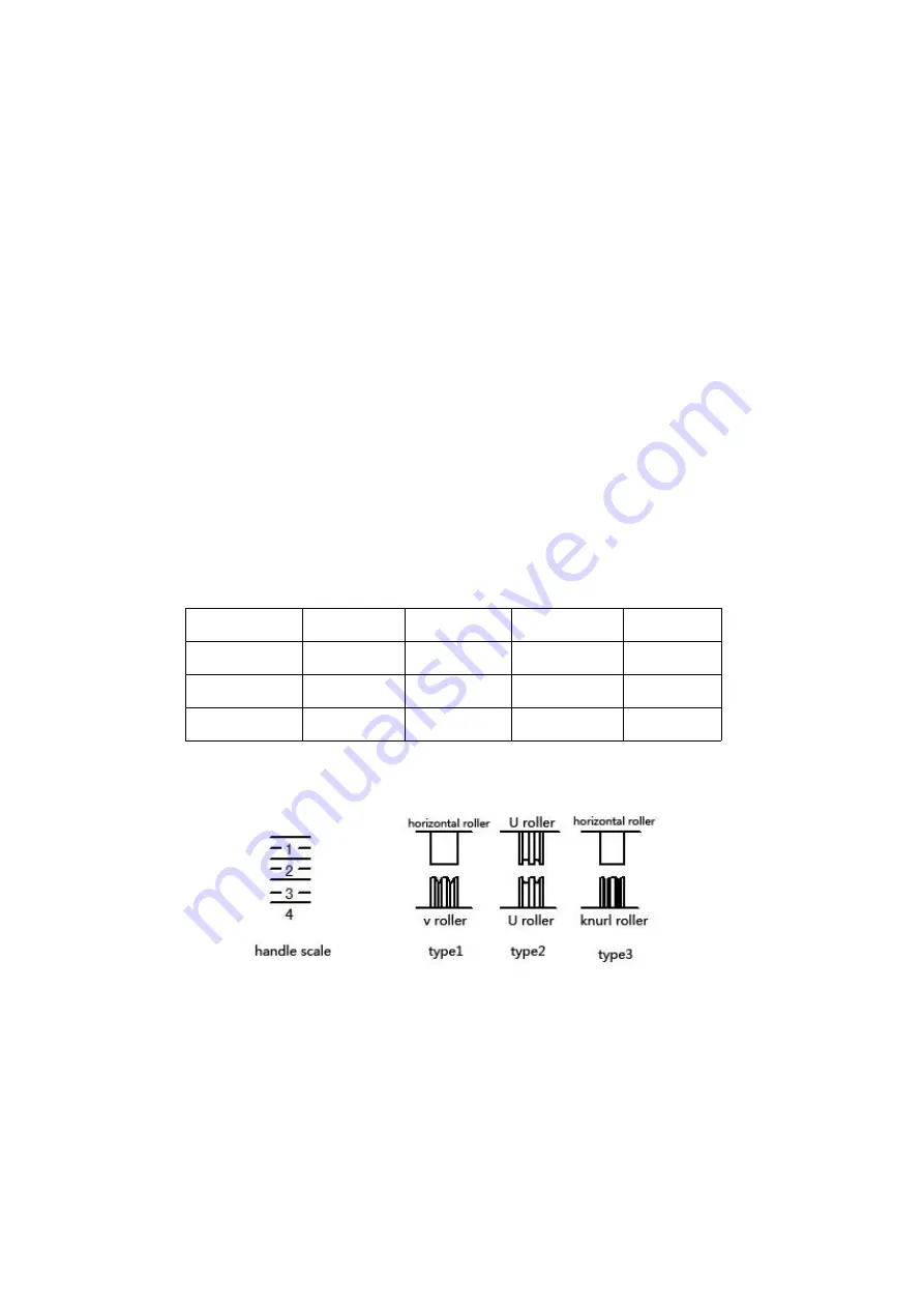
(1) Type 1 is suitable for hard welding wire, such as solid carbon steel, stainless steel wire.
(2) Type 2 is suitable for soft welding wire, such as aluminium and its alloys, copper and
its alloy wire.
(3)Type 3 is suitable for flux cored welding wire.
Use pressure handle to adjust wire feeder roller pressure, keep welding wire into
the catheter evenly and allow a little brake force when the wire come out from the
contact tip, in case wire feed roller slipping
Attention! Overlarge pressure can cause wire to crush and destroy the coating, which will
cause the wire feed roller to abrade fast and wire feeding resistance to increase.
Table11
:
Handle and pressure adjustment reference
φ0.8
φ1.0
φ1.2
φ1.6
1
3
3
2.5
2.5
2
1.5
1.5
1.5
1.5
3
---
---
2
2
Fig 12
:
Wire feeding roller diagram
6.4.4 Wire reel and brake force adjustment
Use wrench loosing braking control screw to adjust the braking force size (as shown in
figure 13), the braking force should be moderate. The braking force should be adjusted to
the appropriate size, so that the wire on the wire reel will not become too loose, in


