20
Section 6: Installing the Control Linkages
Step 5.
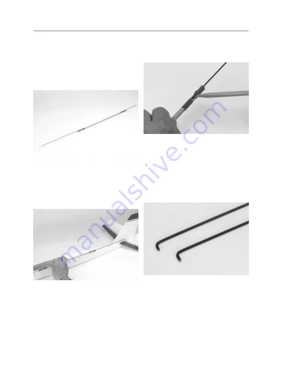
To determine the approximate length of a pushrod,
temporarily tape (using masking tape) one of the 12” pushrod
wires to one end of a wood pushrod, half the distance of the wire
(unthreaded end), onto the wood pushrod. Thread a clevis
approximately 10 turns onto the threaded end of the rod. Repeat
this process with one of the 6” unthreaded rods, however it will
not have a clevis attached. Make sure the metal rods are clear of
the tape near the holes drilled in Step 4.
Step 6.
Position the temporarily assembled pushrod along
the outside of the fuselage, lining it up with the control horn on
the rudder and the servo arm of the rudder servo. Do the same
with the elevator pushrod. Remember the elevator pushrod will
be inserted through the fuselage and exit out the opening at
the aft end.
Step 7.
If necessary, adjust the rods on the wooden pushrod
to allow for a 90-degree bend to be made in the non-threaded
portion of each rod that will be attached to a wooden pushrod.
Step 8.
Mark the rods where the bends will be made in refer-
ence to the marks made on the wooden pushrod (the 1” mark
you made in Step 3).
Step 9.
Disassemble the pushrod and remove the clevis
and tape.
Step 10.
Use a needle nose pliers or standard pliers to make
a 90-degree bend at the mark you made on each rod. Trim off
any excess rod after the bend so it is
1
/
8
” to
3
/
16
” long. The short
portion of the rod that you cut will fit into the holes of the
wooden pushrod without the end extending out of the hole on
the other side. Repeat the process for the 6” unthreaded rod.
Make up the second pushrod following the same procedure.
CONTINUED
Summary of Contents for ULTRA aspire
Page 37: ...37 Notes...
Page 38: ...38 Notes...
Page 39: ...39 Notes...
Page 40: ...Copyright 1999 Horizon Hobby Inc www horizonhobby com...


