background image

26

Hangar 9 P-40B Warhawk 50 ARF

Rudder and Fin Installation

Required Parts

Fuselage assembly 

Rudder

CA hinge (3) 

Fin

Tail gear assembly 

M1.8 x 10 wood screw (2)


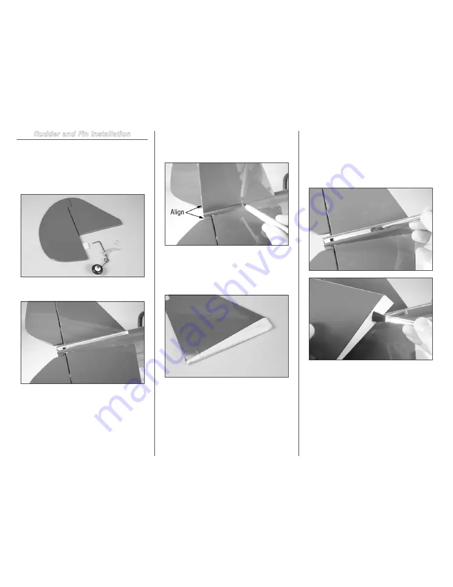
1. Locate the items for this section of the manual.


2. Use a hobby knife with a  #11 blade to remove the 

covering at the rear of the fuselage to expose the slot for the fin.


3. Remove the rudder and hinges from the fin. Slide the 

fin into position on the fuselage. Use a straight edge to align 

the fin with the rear of the fuselage. Use a felt-tipped pen to 

trace the outline of the fuselage on both sides of the fin.


4. Remove the fin from the fuselage. Use a hobby knife 

and a new #11 blade to trim the covering 1/16 inch (1.5mm) 

below the lines drawn in the previous step. Remove the 

covering, exposing the wood at the bottom of the fin. Use a 

paper towel and denatured alcohol to remove the pen lines 

from the fin and fuselage.


Make sure to use a new #11 blade and 

use light pressure to trim only the covering. 

Avoid cutting into the underlying wood, which 

could weaken the structure of your model.


5. Mix 1/2 ounce (15mL) of 30-minute epoxy. Apply 

epoxy to the exposed wood on the bottom of the fin and 

into the slot in the fuselage. Place the fin into position and 

remove any excess epoxy with a paper towel and rubbing 

alcohol. Use a straight edge to align the trailing edge of the 

fin with the fuselage as shown in step 3. Use care not to use 

too much epoxy, as it could accidentally get into the area of 

the elevator joiner wire.

Summary of Contents for P-40B Warhawk 50 ARF

Page 1: ...P 40B Warhawk 50 ARF Assembly Manual ...

Page 2: ...wer 52 Radio 4 channel with 5 servos 4 servos for EP NOTICE All instructions warranties and other collateral documents are subject to change at the sole discretion of Horizon Hobby Inc For up to date product literature visit http www horizonhobby com and click on the support tab for this product Meaning of Special Language The following terms are used throughout the product literature to indicate ...

Page 3: ...ead cap screw 2 Wing attachment M4 flat washer 2 Wing attachment 2mm plywood screw doubler 1 Wing attachment M4 blind nut 2 Wing attachment Landing gear plastic cover 2 Plastic wheel well 2 Retract wheel well template 1 Main wheel placement 6mm x 30mm wood dowel 2 Wing attachment 17mm x 19mm x 10mm hardwood block 4 Aileron servo mount M2 x 10 washer head screw 8 Aileron servo hatch M1 8 x 10 wood ...

Page 4: ...ries Notes on Lithium Polymer Batteries When used improperly lithium polymer batteries are significantly more volatile than alkaline or Ni Cd Ni MH batteries used in RC applications Always follow the manufacturer s instructions when using and disposing of any batteries Mishandling of Li Po batteries can result in fire causing serious injury and damage Small Parts This kit includes small parts and ...

Page 5: ...time and follow the directions UltraCote Covering Colors Olive Drab HANU0904 Gray HANU882 Black HANU874 Recommended Power Setups 4 Stroke Glow Saito 82GK SAIE082BGK or Saito 82 SAIE082B Propeller 14 x 6 EVO14060 90 degree manifold SAI65163 Diverter DUB697 Fuel Filler with T and Overflow Fitting HAN116 2 Stroke Glow Evolution 52NX EVOE0520 Propeller 11 x 6 EVO11060 Muffler BIS04046 Fuel Filler with...

Page 6: ...ing sticks Paper towels Pencil Phillips screwdriver 1 2 Pin vise Pliers Razor saw Reamer Rotary tool Ruler Sanding drum Scissors Side cutters Spray bottle Square Straight edge T pins Tie wraps Toothpicks Vise grips Needle nose pliers Before Starting Assembly Before beginning the assembly of your model remove each part from its bag for inspection Closely inspect the fuselage wing panels rudder and ...

Page 7: ...hree hinges Insert the hinges into the aileron as shown The hinges have a slot in them and must be installed so the slot is perpendicular to the hinge line of the control surface 4 Check the fit of the aileron to the wing panel The aileron should fit tightly against the wing panel Remove the T pins from the hinges Position the aileron so there is an equal gap between the ends of the aileron and wi...

Page 8: ...ur holes Make sure to remove the screw before proceeding to the next step 10 Apply 1 2 drops of thin CA in each of the holes that will accept the servo cover mounting screws 11 Prepare the aileron servo by installing the rubber grommets and brass eyelets as shown in the radio or servo instructions Center the aileron servo using the radio system and place a servo horn on the servo Place the servo o...

Page 9: ...n each hole drilled This will harden the surrounding wood making the screws more secure when installed Do not use a CA accelerator Using an accelerator will not allow the CA to soak into the fibers of the wood hardening the blocks 17 Secure a 6 inch 152mm servo extension to the aileron servo lead using string or a commercially available connector Enlarge the hole in the servo arm using a pin vise ...

Page 10: ...3 32 inch 2 5mm from the edge of the bevel to guarantee the horn is positioned on the hardwood block located in the aileron Use a felt tipped pen to mark the locations for the three mounting screws on the aileron 22 Place a 1 16 inch 1 5mm drill bit in the drill Wrap a piece of tape around the drill bit 5 16 inch 8mm from the end of the drill bit to prevent accidentally drilling through the top of...

Page 11: ...l center the aileron servo Thread the nylon clevis on the pushrod Thread the clevis on enough so the aileron is centered when the clevis is connected to the center hole of the control horn shown below Once set slide the safety tubing over the forks of the clevis to keep the clevis from opening accidentally 28 Repeat Steps 2 though 27 to install the remaining aileron servo Make sure you install the...

Page 12: ...er so it fits equally in both wing panels 5 Make sure the wing panels fit tightly together The wing panels must be joined and taped before the epoxy begins to cure 6 Use 30 minute epoxy to glue the joiner into the wing panels Apply epoxy in the joiner pocket and all sides of the joiner including the top and bottom edges Also coat the exposed wood on the root rib with epoxy Start with one panel ins...

Page 13: ...oubler along the center using a hobby knife and a new 11 blade An indentation in the plate has been made to guide the blade during scoring This will allow it to be bent to conform to the dihedral angle of the wing Use care not to cut too deep into the plate or it could break during installation 10 Position the wing bolt plate on the wing with the scored side facing the wing aligning the holes in t...

Page 14: ...1 2 inch scale wheel 2 Fixed landing gear left and right 1 Locate the items for this section of the manual 2 Test fit the main gear into the wing There is a left and right and the axle will point toward the wing tip when installed Use a pencil to transfer the locations for the mounting screws onto the landing gear rails inside the wing 3 Remove the gear from the wing Use a drill and 5 64 inch 2mm ...

Page 15: ...ver on the landing gear wire and over the coil spring 8 Tape the top edge of the blister down to the wing and then just slightly warm with a heat gun on low to allow the blister to adapt to the wing contour Be careful not to heat the blister too much as you could distort the plastic 9 Use a pin vise and 1 16 inch 1 5mm drill bit to drill six holes three on each side to secure the cover to the wing...

Page 16: ...ding gear wire with the side of the wheel that had the hub cap toward the wing tip 13 Attach the wheel collar to the axle to keep the wheel on the gear The edge of the wheel collar will be flush with the end of the axle Use a 1 5mm hex wrench included to tighten the setscrew Slide the wheel collar installed in step 10 against the wheel but not so tight as it prevents the wheel from rotating smooth...

Page 17: ...mm from the center of the wing Use a felt tipped pen to transfer the position for the wheel well on the wing 4 Use a hobby knife with a new 11 blade to carefully trim the opening for the wheel well in the bottom of the wing Work slowly to avoid any mistakes 5 Use the radio system to move the gear to the DOWN position Test fit the main gear retract into the wing making sure there is clearance at th...

Page 18: ...ition Position the retract aligning the mounting holes to the holes in the mount If the coil spring is not allowing the retract to fit against the mounts you will need to remove a small amount of material from the mounts to clear the spring Use a pencil to mark the location of the spring then use a rotary tool and sanding drum to remove enough material to provide clearance for the coil 10 Attach t...

Page 19: ...s 15 Use a rotary tool and cutoff wheel to trim the length of the axle to 15 16 inch 24mm Use a flat file to remove any burrs left from trimming the axle Use a flat file to make a 1 4 inch 6mm wide flat at the end of the axle 16 Slide the wheel and wheel collar included with the retract on the axle Use a 1 5mm hex wrench to tighten the setscrew onto the axle 17 Attach the included wheel collar to ...

Page 20: ...e axle does not rotate on the gear wire Use a rotary tool and cutoff wheel to trim the length of the strut Replace the axle and tighten the screws using a 2 5mm hex wrench Make sure to use threadlock on the screws to prevent them from vibrating loose 21 Snap the hub cap back into position on the wheel 22 Use a hobby knife and 11 blade and a rotary tool with a sanding drum to make a slot along the ...

Page 21: ...an Installation Required Parts Wing assembly M4 blind nut 2 M4 washer 2 Fiberglass belly pan Fuselage assembly M4 x 45 socket head cap screw 2 1 Locate the items for this section of the manual 2 Use a small C clamp to press the two M4 blind nuts into position from the inside of the fuselage Use a small amount of 30 minute epoxy to each of the prongs to secure the blind nut in the wood Use care not...

Page 22: ... getting all over the wing when gluing the belly pan into position Make sure to use a new 11 blade and use light pressure to trim only the covering Avoid cutting into the underlying wood which could weaken the structure of your model 6 Use medium CA to glue the fiberglass belly pan to the wing Hold the belly pan in position until the CA fully cures Stabilizer and Elevator Installation Required Par...

Page 23: ...t use a felt tipped pen to trace the outline of the fuselage on the top and bottom of the stabilizer 6 Remove the stabilizer from the fuselage Use a hobby knife and a new 11 blade to trim the covering 1 16 inch 1 5mm inside the lines drawn in the previous step Remove the covering exposing the wood at the center of the stabilizer 7 Use a hobby knife with a 11 blade to remove the covering from the e...

Page 24: ...er of the stabilizer Make sure to apply epoxy on both the top and bottom of the stabilizer 12 Position the stabilizer following steps 5 through 7 Remove any excess epoxy from the stabilizer and fuselage using denatured alcohol and a paper towel 13 Use a pin vise and 1 16 inch 1 5mm drill bit to drill a hole in the center of each hinge slot This creates a tunnel for the CA to wick into creating a b...

Page 25: ...he balance tabs on the elevator and stabilizer 19 Saturate each of the hinges with thin CA on both the top and bottom of the hinge Set the assembly aside to cure Allow the CA to cure WITHOUT using CA accelerator This is necessary to allow the CA to soak into the hinge creating the best bond between the hinge and surrounding wood 20 Once the CA and epoxy has cured check that all the hinges are secu...

Page 26: ...blade to trim the covering 1 16 inch 1 5mm below the lines drawn in the previous step Remove the covering exposing the wood at the bottom of the fin Use a paper towel and denatured alcohol to remove the pen lines from the fin and fuselage Make sure to use a new 11 blade and use light pressure to trim only the covering Avoid cutting into the underlying wood which could weaken the structure of your ...

Page 27: ...e in the rudder where they contact each other Insert the tail wheel wire into the rudder Use a paper towel and rubbing alcohol to remove any excess epoxy before it can cure Use low tack tape to hold the wire in position until the epoxy has fully cured 9 Use a pin vise and 1 16 inch 1 5mm drill bit to drill a hole in the center of each hinge slot This creates a tunnel for the CA to wick into creati...

Page 28: ...en the surrounding wood Allow the CA to cure without the use of an accelerator for the best results 13 Attach the aluminum plate using two M1 8 x 10 wood screws Use a 2 Phillips screwdriver to tighten the screws Remove the setscrews on the wheel collars using a 1 5mm hex wrench for the tail wheel and mounting plate and apply threadlock to the setscrews Tighten the setscrews to secure their positio...

Page 29: ...or the radio tray 5 Use four 6 32 x 3 4 inch socket head cap screws and four 6 washers to attach the preassembled plywood motor mount box to the firewall Make sure the smaller hole in the motor mount box aligns with the hole in the firewall and that the center lines on the box align with those on the firewall Make sure to use threadlock on the screws to prevent them from vibrating loose CAUTION Cu...

Page 30: ... to make a hole to pass the battery lead servo lead and switch into the fuselage Use a tie wrap not included to secure the ESC so it does not move from position Secure a 6 inch 152mm servo extension to the receiver lead of the ESC Pass the leads for the receiver battery and switch harness through the opening made in the previous step 10 Connect the motor leads Make sure they won t interfere with t...

Page 31: ...ed to the servo Use a pencil to mark the location for the screws that will secure the servo to the servo tray 4 Use a pin vise and 1 16 inch 1 5mm drill bit to drill the holes for the four mounting screws 5 Use a 1 Phillips screwdriver to run a servo mounting screw in each of the four holes Make sure to remove the screw before proceeding to the next step 6 Apply 1 2 drops of thin CA in each hole d...

Page 32: ...lace the remote receiver as far away from the main receiver as possible for the best radio reception 10 The battery is secured in the fuselage using the hook and loop strap We placed a piece of hook and loop tape on the battery to keep the battery from moving inside the fuselage Glow Engine Installation Required Parts Fuselage assembly Throttle pushrod 290mm Pushrod tube 200mm Engine mount right a...

Page 33: ...e installed Note that two blind nuts have been trimmed to clear the triangle stock on the left side of the firewall inside the fuselage 6 Use four 6 32 x 3 4 inch socket head cap screws and four 6 washers to attach the two nylon engine mounts to the firewall Do not fully tighten the screws at this time 7 Locate the 8 inch 200mm pushrod housing Use medium grit sandpaper to roughen two 1 2 inch 13mm...

Page 34: ...he pushrod wire 9b Four stroke throttle pushrod When installing a four stroke engine the Z bend in the pushrod will connect to the carburetor arm Remove and rotate the carburetor as shown so the carburetor arm is on the side shown 10 Attach the engine to the nylon engine mount using four 4 40 x 1 inch socket head cap screws four 4 washers and four 4 40 lock nuts Place the washer on the bolt before...

Page 35: ...being transferred to the servo Use a pencil to mark the location for the screws that will secure the servo to the servo tray 4 Use a pin vise and 1 16 inch 1 5mm drill bit to drill the holes for the four mounting screws 5 Use a 1 Phillips screwdriver to run a servo mounting screw in each of the four holes Make sure to remove the screw before proceeding to the next step 6 Apply 1 2 drops of thin CA...

Page 36: ...fuselage using the hardware provided with the switch Use a pin vise and 5 64 inch 2mm drill bit to drill through the backing plate located behind the pilot holes for the switch There are multiple locations for the switch so choose the one that best suits your application 11 Slide the radio tray into position Use an M3 x 10 socket head screw and M3 washer to secure the tray in the fuselage Connect ...

Page 37: ...nter of the horn and the 645mm elevator pushrod connects to the horn 9 16 inch 14mm from the center of the arm Secure the arms using the screws from the servos and a 1 Phillips screwdriver 4 Use a hobby knife and 11 blade to cut a 1 4 inch 6mm piece of silicone tubing Slide the tubing on a nylon clevis then thread the clevis on the rudder pushrod Remove the backplate from the control horn then con...

Page 38: ...throttle and move the pushrod to close the throttle Use a 1 5mm hex wrench to tighten the setscrew securing the pushrod in the connector Check the operation of the throttle The carburetor should be open slightly when the trim is centered but closed if the trim is set to close the throttle It may be necessary to adjust the throw at the radio slightly to operate the throttle from fully open to fully...

Page 39: ...ng 5 Use hobby scissors as well as a rotary tool with a sanding drum to make a notch in the cowl to clear the propeller shaft This will make installing the cowl easier 6 Remove the cowl and make any necessary openings using hobby scissors and a rotary tool with a sanding drum You may need to install the engine at this time Slide the cowl into position then the spinner backplate Use the spinner ada...

Page 40: ...ors and a rotary tool with a sanding drum to remove the material necessary on the cowl to clear the muffler Secure the cowl to the fuselage using the four M3 x 10 black washer head screws and a 1 Phillips screwdriver When installing the fuel filler in the cowl make sure to position it lower on the cowl so it will not interfere with the installation of the exhaust stacks 12 Secure the Spinner backp...

Page 41: ...lage hatch onto the cowling The exhaust stack is placed 9 16 inch 14mm below the line and 11 8 inch 18mm forward of the rear edge of the cowl Use a small amount of silicone adhesive to glue the exhaust stacks to the cowling Use low tack tape to hold the exhaust stacks in position until the glue fully cures Front Canopy and Machine Gun Installation Required Parts Fuselage assembly Wing assembly Can...

Page 42: ... Insert the plastic sheet then check the clearance between the plastic sheet and canopy Once it fits without interference use canopy glue to glue the plastic sheet into position 6 Optional Trim the bottom of the pilot using a hobby knife with a 11 blade and razor saw The overall height of the pilot will be 25 8 inches 66mm Use 30 minute epoxy to secure the pilot figure in the cockpit 7 Use canopy ...

Page 43: ...to rest overnight so the remaining water can evaporate Use the following photos as a reference when installing the decals Two different trim schemes have been provided Center of Gravity Required Parts Assembled model An important part of preparing the aircraft for flight is properly balancing the model CAUTION Do not inadvertently skip this step 1 Attach the wing to the fuselage Make sure to conne...

Page 44: ...ches 10 mm Down 9 32 inches 7 mm Elevator High Rate Up 11 16 inches 18 mm Down 11 16 inches 18 mm Low Rate Up 7 16 inches 11 mm Down 7 16 inches 11 mm Rudder High Rate Right 2 inches 51 mm Left 2 inches 51 mm Low Rate Right 13 16 inches 30 mm Left 13 6 inches 30 mm These are general guidelines measured from our own flight tests You can experiment with higher rates to match your preferred style of ...

Page 45: ...e iii modification of or to any part of the Product iv attempted service by anyone other than a Horizon Hobby authorized service center or v Products not purchased from an authorized Horizon dealer OTHER THAN THE EXPRESS WARRANTY ABOVE HORIZON MAKES NO OTHER WARRANTY OR REPRESENTATION AND HEREBY DISCLAIMS ANY AND ALL IMPLIED WARRANTIES INCLUDING WITHOUT LIMITATION THE IMPLIED WARRANTIES OF NON INF...

Page 46: ...ur Product will be serviced or replaced free of charge Service or replacement decisions are at the sole discretion of Horizon Non Warranty Service Should your service not be covered by warranty service will be completed and payment will be required without notification or estimate of the expense unless the expense exceeds 50 of the retail purchase cost By submitting the item for service you are ag...

Page 47: ...th comparable standards B RADIO CONTROL RC 1 All pilots shall avoid flying directly over unprotected people vessels vehicles or structures and shall avoid endangerment of life and property of others 2 A successful radio equipment ground range check in accordance with manufacturer s recommendations will be completed before the first flight of a new or repaired model aircraft 3 At all flying sites a...

Page 48: ...by logo are trademarks or registered trademarks of Horizon Hobby Inc DSMX is a trademark of Horizon Hobby Inc registered in the US The Spektrum trademark is used with permission of Bachmann Industries Inc Saito is a trademark of Saito Seisakusho Co Ltd Japan All other trademarks service marks and logos are the property of their respective owners ...

Reviews: