


www.han-bond.com
51
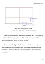
Figure 16 X/Y coincidence effect diagram
("---black line" is ink jet lines,
---
"red line" is cutting line)
Note: all of the following parameters must be adjusted during machine in the
standby mode or during ink jet period. If it’s in the parameters of the
adjustment during the cutting process are not valid.
The first step: take (Figure 16) "A reference position" as an example, when
the cutting line in the right-hand of ink jet line, need to decrease the control
panel item 6 [Y axis coincides set] corresponding value, contrary to increase
numerical;
Summary of Contents for HB Series
Page 15: ...www han bond com 14 2 4 circuit diagram...
Page 25: ...www han bond com 24...
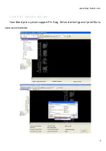
Page 27: ...www han bond com 26 Select browse the computer to find the driver software R Click browse...
Page 29: ...www han bond com 28 Load in Click close Installation process complete...
Page 32: ...www han bond com 31 Click next NEXT...
Page 33: ...www han bond com 32 Click next NEXT Click Install...
Page 34: ...www han bond com 33 Installing...
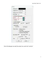
Page 48: ...www han bond com 47 Enter the design size and the actual size and click confirm...


