


www.han-bond.com
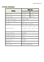
10
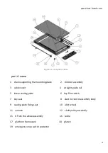
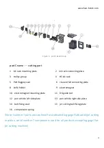
Figure 4 A component name
part A name
1 chain supporting the mounting plate
2 X motor assembly
3 cable cover
4 straight guide rail
5 lower sealing plate
6 key film switch
7 key seat
8 electric control assembly body
9 sealing plate fixing seat
10 idler wheel
11 column
12 shaft pulley assembly
15 X from the wheel assembly
16 table
17 platform framework
18 platen
19 emergency stop switch protector
Summary of Contents for HB Series
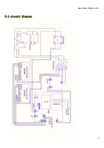
Page 15: ...www han bond com 14 2 4 circuit diagram...
Page 25: ...www han bond com 24...
Page 27: ...www han bond com 26 Select browse the computer to find the driver software R Click browse...
Page 29: ...www han bond com 28 Load in Click close Installation process complete...
Page 32: ...www han bond com 31 Click next NEXT...
Page 33: ...www han bond com 32 Click next NEXT Click Install...
Page 34: ...www han bond com 33 Installing...
Page 48: ...www han bond com 47 Enter the design size and the actual size and click confirm...


