035-17477-002 Rev. D (1202)
14
Unitary Products Group
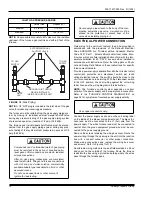
ACCESSORY CONNECTIONS
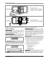
The furnace control will allow power switching control of vari-
ous accessories. Refer to Figure 15, for connection details.
ELECTRONIC AIR CLEANER CONNECTION
Two 1/4" spade terminals (EAC and EAC N) for electronic air
cleaner connections are located on the control board. The
terminals provide 115 VAC (1.0 amp maximum) during circu-
lating blower operation.
HUMIDIFIER CONNECTION
Two 1/4" spade terminals (HUM and HUM N) for humidifier
connections are located on the control board. The terminals
provide 115 VAC (1.0 amp maximum) during heating system
operation.
TWINNING
When two furnaces are installed using the same duct system,
it is very important that the two furnace circulating air blowers
operate simultaneously. If one blower starts before the sec-
ond blower, the duct system will become pressurized with air
and the second blower will be made to turn backwards. Dur-
ing heating operation, this will cause overheating of the
second furnace, possibly causing an unsafe condition and
damage to the furnace. If twinning of two furnaces is desired,
it is necessary to use the accessory twinning kit that is
designed for use with these furnaces.
COMBUSTION AIR AND VENT SYSTEM
1.
Two-pipe with a sealed combustion intake/vent system
using outdoor combustion air.
2.
Single pipe vent system using combustion air from the
area surrounding the furnace.
3.
Two-pipe intake/vent system using combustion air from a
ventilated attic space and a vent pipe to the outside.
Be sure to follow the appropriate venting section details,
related information and limitations for your type of installation.
METHOD ONE: TWO PIPE SEALED
COMBUSTION AIR & VENT SYSTEM
COMBUSTION AIR INTAKE/VENT CONNECTIONS
This type installation requires outdoor combustion air. Two
separate, properly-sized pipes must be used. One bringing
air from the outdoors to the furnace combustion air intake col-
lar on the burner box, and a second pipe from the furnace
vent connection (top right of unit) back to the outdoors.Figure
16 or 17.
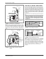
FIGURE 15 :
Accessory Connections
This furnace is certified to be installed with one of three
possible intake/vent configurations.
115 VOLT
HUMIDIFIER
115 VOLT
ELECTRONIC
AIR CLEANER
BLK
WHT
EAC HOT
HUM. HOT
BLK
WHT
EAC
HUM
EAC
HUM
NEUTRALS
SWITCHED
CIRCUITS
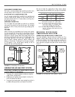
Furnace Intake / Vent Connection Size (All Models)
40 - 100 MBH
120 - 140 MBH
Intake
2”
3"
Vent
2”
2"
*
*.
Vent must be increased to 3" on this model.
Note 1:Any vent pipe size change must be made out-
side furnace casing in a vertical pipe section
to allow proper drainage of condensate.
Note 2: An offset using two 45 degree elbows will be
required for plenum clearance when the vent
is increased to 3”.
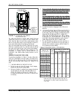
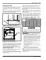
FIGURE 16 :
Air Intake and Vent Locations - Upflow
VENT PIPE
CEMENTS
INTO SOCKET
JUST UNDER
TOP PANEL
COMBUSTION AIR
PIPE PASSES
THROUGH TOP PANEL
CONNECTS TO
COLLAR ON TOP
OF BURNER BOX


