background image


Wireless Communications Setup 


Configuring the A-1519/1520 Target System Group 


A Target System Group consists of one Radio Transceiver/Hub and up to 99 Type II Targets. There can 

be up to ten Target System Groups consisting of 99 targets per group. 


To configure multiple targets and one Radio Transceiver as a System Group

1.


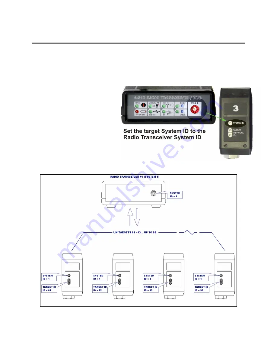
Set all targets to the same System ID, 

ranging from 1 to 9.   

2.


Set each target in the System Group 

to a different Target Network ID, 

ranging from 01 to 99 (Target 

Network ID: 00 is reserved for 

factory use). 

3.


Set the Radio Transceiver to the 

same System ID as the Targets in the 

same System Group. 


Figure 8 – 

Radio Transceiver and Target System ID 


Figure 9 – 

Target System (System ID: 1) with 4 targets (Target Network ID: 01 to 03 and 99) 

Summary of Contents for R-1307

Page 1: ......

Page 2: ...rticles of equipment manufactured by other companies and limited by a warranty extending for less than one year In such an event the more limited warranty applies to said instrument or article of equipment This warranty shall not apply to any instrument or other article of equipment which shall have been repaired or altered outside the Hamar factory or which has been subject to misuse negligence o...

Page 3: ...the A 1519 1520 Type II Configuration Utility 14 Installation 14 Users Database 14 Initial Setup 14 Editing the User Database 15 Logging In 16 Startup 17 Troubleshooting 18 Switching Between Normal Application Mode and Configuration Mode 18 Diagnostic Readout Normal Application Mode 19 Diagnostic Readout Debug Mode 20 Diagnostic Readout Advanced Functions 21 Updating the Firmware 22 Configuration ...

Page 4: ...rnal temperature sensor Improved Background light noise suppression Internal dampening by averaging of 2 to 64 laser position scans Identifying Target Features 1 Right Side Auxiliary Ports 2 Front View 3 Left Side ID Switches 4 Rear View 1 1 Auxiliary Port Expansion Port 1 2 USB Port Used to update target firmware upload calibration data configure operating parameters and run diagnostics Can also ...

Page 5: ...s battery life by approximately 10 percent Note The shelf life of lithium polymer batteries is 2 3 years under optimal conditions Expect the battery capacity to drop to 80 percent after 500 charge discharge cycles To extend battery life keep it away from heat for example inside a closed vehicle in full sun and for best results charge the battery to 100 percent of capacity and then allow it to disc...

Page 6: ...1307W 2 4ZB is designed to suit a user s specific needs with the R 1307 2 4ZB and the R 1307W 2 4 ZB models featuring ZigBee radio technology The readout is available with a radio frequency of either 900 MHz or 2 4 GHz and can be used as the primary readout or as an additional readout to copy position data captured by another R 1307 R 1307 Control Panel Figure 4 shows the features of the R 1307 Co...

Page 7: ...e adequate power 5V 400 mA through the USB port Note When using the USB Extender cable extension kit plug the A 910 2 4 into an A C power supply 5 Antenna See Appendix C on Page 30 for radio specification details MODEL NUMBER PRIMARY FREQUENCY A 910 900 900 MHz A 910 2 4 2 4 GHz Setting up the A 910 Transceiver Note Do not plug the A 910 USB cable into your computer until Step 3 Doing so may cause...

Page 8: ...es with the R 1307 2 4ZB models and plugs directly into any unused computer USB port to communicate directly with the targets Utility software is provided for driver installation setup and configuration For detailed information see Appendix I beginning on Page 43 ...

Page 9: ...he Readout Function to Local Target Press the MENU button until the upper display shows Use the UP and DOWN arrow keys to select 6 Select the PSD descriptor applicable to your target Press the MENU button until the upper display shows where designates the target number Each R 1307 has three target descriptors TGT 0 for HLI use only Do not use TGT nn P 10 10 pulsed beam mode TGT nn F 10 10 fixed be...

Page 10: ... display shows with the current System ID blinking Use the UP and DOWN arrow keys to set the System ID Note that nn must be set to the same number as the channel switch setting of the A 910 radio transceiver see Figure 5 5 Miscellaneous Display Messages Startup Message Lower Display shows firmware Revision Number 3 moving dots Wireless target is not responding to a polling request from Readout Che...

Page 11: ...rgets and one Radio Transceiver as a System Group 1 Set all targets to the same System ID ranging from 1 to 9 2 Set each target in the System Group to a different Target Network ID ranging from 01 to 99 Target Network ID 00 is reserved for factory use 3 Set the Radio Transceiver to the same System ID as the Targets in the same System Group Figure 8 Radio Transceiver and Target System ID Figure 9 T...

Page 12: ...der Host computer control the radio transceiver transmits a message called a polling request that contains the Target Network ID of one specific target All targets receive all polling requests but only the target with a Network ID matching the ID contained in the polling message will reply Transmit Data to the Host There are three rotary DIP switches located on the right side of the target shown i...

Page 13: ...for easy removal and placement 1 Mount the Charging Station to the wall or any other suitable vertical support structure using two screws of the appropriate type for the mounting structure refer to Figure 11 and for dimensional information 2 Plug in the Charging Station power supply 3 To charge the Targets place each target in one of the four cradles Slide the target down until it is fully seated ...

Page 14: ...nly the included Hamar Laser power supply Use of another power supply may void the warranty of the Charging Station and targets Input 120VAC 60Hz US Output 7 5VDC 2A Charging Rate 400mAH Cradle Target Maximum Protection Short circuit and reverse polarity protection Explosive Atmosphere Not approved ...

Page 15: ... the CD ROM icon and open it Click the USB Driver folder see Figure 13 3 Locate the Preinstaller exe icon and click to initiate the installation process The Install Driver dialog box displays see Figure 14 4 Click Browse to select an installation folder different from the default folder optional 5 Click Install to continue Once the installation is complete the Installation Successful message displ...

Page 16: ... Transceiver and then to any available USB port on the computer The Windows Found New Hardware Wizard see Figure 16 and Figure 17 displays a number of times Each time the Wizard displays select Install software automatically Click Next Wait for the next step to complete Click Finish see Figure 18 Figure 16 Windows XP Hardware Wizard Figure 17 Windows XP Hardware Wizard Last Step Installation of th...

Page 17: ...files always keep the newest files 6 After Setup completes click Start Program Files Hamar Laser Utilities Click A 1519 Type II Configuration Utility to start the program Users Database The Configuration Utility uses a user database to assign permission levels to multiple users Users must log in with a user name and password to configure the target update firmware etc The person designated as the ...

Page 18: ...s cannot make changes to the Primary Administrator account Power User This user can access to all program features but does not have permission to access the Users Database Operator This user has access to basic configuration features but does not have permission to Update Firmware or Calibration Data and Critical Configuration parameters User Not in Database This user has access to Target Status ...

Page 19: ...s Database and a valid password for that user the OK button is enabled to indicate that the password is valid Note that the Users button is also enabled because user Admin2 is a Backup Administrator with permission to edit the Users Database To have the application remember your User Name and password for future login check Remember Password see Figure 24 Do not check Remember Password when loggin...

Page 20: ...proximately once every three seconds Figure 27 Target detected in Configuration Mode Target Connected in Application Mode Figure 28 The target must be in Application Mode to be used with standard applications that require position information in standard packet format In addition Diagnostic Readout is only functional in Application Mode When the target is in Application Mode the Status LEDs see Fi...

Page 21: ...get Ensure that the target is ON The center LEDs see Figure 1 Front View 2 1 should be lit continuously if the target is in Application Mode or blinking once every three seconds if the target is in Configuration Mode Ensure that the laser is ON and scanning across the position sensor see Figure 1 Front View 2 4 Click the SCAN PORTS button to rescan the ports see Figure 25 Switching Between Normal ...

Page 22: ... The Periodicity Sync indicator _ The Incident Light Level bar _ The Battery Charge indicator Center Packet data Green fields indicate normal values Yellow fields indicate caution values are borderline normal Red fields indicate abnormal values Bottom Communication Error Statistics Peak Noise peak to peak over the specified period Network ID of target being polled for data The polling interval Ext...

Page 23: ...tion Sensor readings Power Supply Voltages Beam on Sensor Time and Incident Noise Characteristics 1 Set the target to DEBUG B Packet Mode see Figure 35 The Diagnostic Readout window displays see Figure 36 2 Click START POLLING TARGET the button title changes to STOP POLLING TARGET Figure 36 Diagnostic Readout Debug Mode Figure 35 Non standard Modes ...

Page 24: ... with an xls extension you will be able to import the data directly into Microsoft Excel 5 Click Stop Polling Target to stop saving data Dynamic Plot Check Underlay Position Plot The position readings will plot behind the Numerical Position Display Plot Options Check Show Plot Only to hide the numerical position By default the plot will show 100 samples along the X axis The slide bar below Underla...

Page 25: ...utility to finish processing the file for uploading to the target see Figure 40 When the file processing completes verify that you want to update the target firmware with the specified file version see Figure 39 The firmware version that is presently installed in the target is shown in the Target Properties area of Figure 40 In that example the target is using firmware version 7 033 Click YES to u...

Page 26: ...le the firmware upload is in progress see Figure 41 When the upload completes an EOF End of File verification message displays see Figure 42 Click OK Figure 41 Target firmware upload in progress Figure 42 End of File Verification message ...

Page 27: ...ight sources such as fluorescent lighting fluctuates at the AC line frequency or twice the AC line frequency Set the Light Periodicity to the AC line frequency at the location where the target will be used as follows 60 120Hz United States 50 100Hz or 60 120Hz other countries Note DEBUG is for Hamar Laser use only Avg Samples Internal Average Enabled Position Average of Samples Vibration and air t...

Page 28: ...or in the back The Type I Unitarget is smaller and only has a single circular connector in the back There are two types of Type II Unitargets in the field The A 1519 targets can be identified by the sensor type visible through the front window as shown in Figure 44 Type II Legacy Single Axis Sensor Compatible with radio version of the Type I Unitarget Supports all scanning lasers Does not support ...

Page 29: ...ver most assistance is limited to information regarding the structure of the calibration file Hamar Laser Calibration Method The A 1519 A 1520 targets are calibrated using a proprietary automated station designed by Hamar Laser The calibration station is comprised of a precision motorized linear stage using an interferometer as the position reference Under computer control the target is displaced ...

Page 30: ... Number Sensor Resolution Linearized Accuracy Range A 1519 0 00002 in 0 0005 mm 0 00015 in 0 0035 mm 1 0 in 24 mm A 1520 0 00001 in 0 00025 mm 0 00006 in 0 0015 mm 0 2 in 5 mm Range may be limited by obstructions antenna type and orientation Outdoors line of sight range with dipole antenna may be greater Radio Specifications 900 MHz Models A 1519 900 A 1520 900 2 4 GHz Models A 1519 2 4 A 1520 2 4...

Page 31: ...d This makes is very likely that the error in measurement at the point where the target is zeroed is nearly identical to the error in each subsequent measurement because the difference in sensor area between the two points is less than 1 mm So in effect the error really does not matter it s like having the same error offset at each point The errors start becoming important only when large deviatio...

Page 32: ...rea is 1 micron or less Approx 4 mm of measuring area each vertical line on the graph equals 1 mm Total Error 3 3 microns 2 microns 2 microns 0 000 Each green vertical line equals 1 mm of measuring area on the detector The total area here is 8 mm ...

Page 33: ...ot recommended IC Industry Canada Certification Contains Model 24XStream Radio 2 4 GHz IC 4214A 12008 Complies with IC ICES 003 Complies with ETSI France France imposes restrictions on the 2 4 GHz band Go to www art telecom Fr or contact MaxStream for more information Norway Norway prohibits operation near Ny Alesund in Svalbard More information can be found at the Norway Posts and Telecommunicati...

Page 34: ...dustry Canada Certification Contains Model 9XCite Radio 900 MHz IC 4214A 9XCITE Agency Certifications for the XBee 802 15 4 Series 1 FCC United States of America Certification Contains FCC ID OUR XBEE The enclosed device complies with Part 15 of the FCC Rules Operation is subject to the following two conditions 1 this device may not cause harmful interference and 2 this device must accept any inte...

Page 35: ...32 Appendix D Dimensional Drawings A 1519 Type II Universal Wireless Target All dimensions in inches ...

Page 36: ...33 A 1519 RS 485 Cable Diagram ...

Page 37: ...34 Appendix E Using the A 151945 4 Port Target Communication Wired Hub ...

Page 38: ...ater than or equal to the scan rate For most Hamar Laser scanning lasers the recommended polling rate is 4 times second 250 milliseconds interval Polling the same target at a rate faster than the laser scan rate is pointless because the target will not reply with a new data packet until the position has been refreshed by a new laser scan Standard procedure for polling a target a Initialize the Act...

Page 39: ... Information Page 38 VP VERTICAL POSITION COUNTS 32768 TO 32767 1µm 2 COUNTS A 1519 1µm 4 COUNTS A 1520 VCO SENSOR CENTER OFFSET 4000 TO 4000 1µm 2 COUNTS A 1519 1µm 4 COUNTS A 1520 BAT BATTERY VOLTAGE 0 TO 5000 MILLIVOLTS TEMP INTERNAL TEMPERATURE COUNTS 160 TO 800 1 COUNT 1 16ºC CHK PACKET CHECKSUM Notes Two byte integer values for example SN CHK are in least significant byte most significant by...

Page 40: ...2767 1µm 2 COUNTS A 1519 1µm 4 COUNTS A 1520 VCO VERTICAL CENTER OFFSET 4000 TO 4000 1µm 2 COUNTS A 1519 1µm 4 COUNTS A 1520 BAT BATTERY VOLTAGE 0 TO 5000 MILLIVOLTS TEMP INTERNAL TEMPERATURE COUNTS 160 TO 800 1 COUNT 1 16ºC HP HORIZONTAL POSITION COUNTS 32768 TO 32767 1µm 2 COUNTS A 1519 1µm 4 COUNTS A 1520 HCO HORIZONTAL CENTER OFFSET 4000 TO 4000 1µm 2 COUNTS A 1519 1µm 4 COUNTS A 1520 CHK PACK...

Page 41: ...ASER DETECTION STATUS BIT 7 BIT 6 BIT 5 BIT 4 BIT 3 BIT 2 BIT 1 BIT 0 0 1 1 1 0 1 0 0 BIT 7 0 0 0 0 0 0 0 0 1 1 1 1 1 1 1 1 BIT 6 0 0 0 0 1 1 1 1 0 0 0 0 1 1 1 1 BIT 5 0 0 1 1 0 0 1 1 0 0 1 1 0 0 1 1 BIT 4 0 1 0 1 0 1 0 1 0 1 0 1 0 1 0 1 ILL 0 1 2 3 4 5 6 7 8 9 1 0 1 1 1 2 1 3 1 4 1 5 PERIODICITY 50 100Hz 60 120Hz NONE UNSTABLE BIT 3 0 0 1 1 BIT 2 0 1 0 1 BIT 1 1 AUX USB PORT ACTIVE 0 RADIO RS 485...

Page 42: ... a small screwdriver Check A C power source Use second A C power supply if available 5 Noisy target A 1519 1520 readings on PDA NOTE On average the user can expect 00002 in ft to 00005 in ft 0 0025 mm m 0 004 mm m of noise in good operating conditions Check for vibration in laser instrument stand tripod or surface the laser is sitting on If laser is mounted on a machine tool try turning machine to...

Page 43: ...tion is connected to USB port Ensure the correct COM port is selected for the USB bridge controller see Windows Device Manager must be lower than COM10 Check Device Manager in Windows Control Panel Set COM port for USB bridge controller lower than COM10 Ensure the correct target ID is chosen in Machine Tool Geometry or Read8 software Ensure channel setting system ID on A 1519 1520 matches the sett...

Page 44: ...is connected to the laptop s USB port If problem persists contact HLI 13 PDA locks up Hit RESET switch Dell PDA RESET is on right hand side of the back of PDA near the lower right corner of the radio module HP IPAQ RESET is on bottom end of PDA 14 PDA turns off automatically Check the Power Saving Options in the PDA see PDA manual for details 15 PDA is frozen Check the lock switch on the side of t...

Page 45: ...s the type intended for nail polish removal NOTE When cleaning precision optics even with the best quality optical cleaning tissue use gentle pressure to avoid scratching the surface or damaging the optical coating s Always wipe using a figure eight motion in one direction begin at the top and work toward the bottom in a figure eight motion Use only moistened not soaked optical cleaning tissue Swa...

Page 46: ...dows 2000 Windows XP etc and open the folder 5 Locate the CP210x_VCP icon and click to initiate the installation process The Install Driver dialog box displays 6 Click Browse to select an installation folder different from the default folder optional 7 Click Install to continue Once the installation is complete the Installation Successful message displays see Figure 45 Figure 45 USB Common Driver ...

Page 47: ...e utility does not automatically detect the COM port it must be manually selected 3 The Target System ID or R 1307 CH channel is the number associated with the A 1519 1520 targets or R 1307 Readout If using both the A 1519 1520 and an R 1307 Readout both need to be set to the same System ID and channel see Figure 48 For further information see Manually Selecting the COM Port on Page 45 Figure 47 A...

Page 48: ...t button and select Control Panel 2 Click the System icon 3 In the System window click on the Device Manager link located under the System heading 4 In Device Manager scroll down to Ports Expand the listings under Ports to reveal all the ports installed 5 Locate SILICON LABS CP210x USB to UART Bridge COM x see Figure 49 6 Note the COM Port listed and select that COM Port in the A 910 Zigbee Utilit...

Page 49: ...ve background light causes a warning to display on the PDA an optional light shield may be installed on the A 1519 Target as follows 1 Roll each set screw in Loctite 2 Install set screws in the holes on the A 1519 Target 3 Install the light shield to the target ...

Reviews: