4
The A-910 Radio Transceiver/Hub
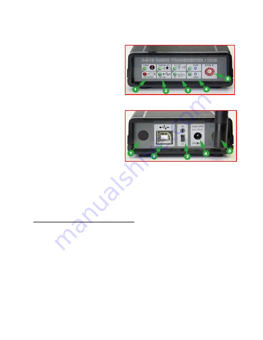
Front Panel Features
1.
Power ON indicator and Low Battery
indicator
2.
Internal backup battery charging
indicator and USB LINK
ESTABLISHED indicator
3.
TX indicator:
blinks when device is
transmitting data to the target(s)
4.
RX indicator:
blinks when the device is
receiving data from targets or other
transceivers.
5.
System ID setting switch:
set to the same
number as the R-1307’s CH (Channel)
number.
Rear Panel Features
1.
Not used
2.
USB/Data I/O Port
3.
Power Switch
4.
External power supply:
required
only for
computers that cannot provide adequate
power (5V, 400 mA) through the USB
port.
Note:
When using the USB Extender™
cable extension kit, plug the A-910-2.4
into an A/C power supply.
5.
Antenna
See Appendix C on Page 30 for radio specification details.
MODEL NUMBER
PRIMARY FREQUENCY
A-910-900
900 MHz
A-910-2.4
2.4 GHz
Setting up the A-910 Transceiver
Note:
Do not plug the A-910 USB cable into your computer until Step 3. Doing so may cause computer
lockup.
1.
Using the CD provided, install the USB Common Driver.
2.
Using a small screwdriver, change the System ID on the front panel of the A-910 to
1
.
3.
Connect the USB cable to the back of the A-910 and to the USB port of your desktop or laptop
computer.
Figure 5 –
The A-910 Radio Transceiver/Hub FRONT PANEL
Figure 6 –
The A-910 Radio Transceiver/Hub REAR PANEL


