Exhaust Alert Mk3
Installation & Operating Instructions
THE SCIENCE OF SILENCE
© Halyard 2020. All Rights Reserved.
Page 1: ...Exhaust Alert Mk3 Installation Operating Instructions THE SCIENCE OF SILENCE Halyard 2020 All Rights Reserved...
Page 2: ...the Components 4 3 1 Fitting the sensor 4 3 2 Fitting the Connection Block 5 3 3 Fitting the Master Gauge 5 Section 4 Wiring Connections 7 4 1 Connection Block 7 4 2 Wiring Master Gauge 7 4 3 Circuit...
Page 3: ...m careless use of hand tools lifting equipment power tools or unaccepted maintenance or working practices Because of the possible danger to persons or property from accidents that may result from the...
Page 4: ...t system immediately after the engine exhaust outlet The cooling water reduces the temperature of the exhaust system and reduces exhaust noise Should the cooling water flow be blocked or substantially...
Page 5: ...hs Electrical tie wraps or cable clips to secure the wiring to suitable supports A small electrical screwdriver to fit the terminals on the connection block Spanners to fix the sensors to the flexible...
Page 6: ...xhaust elbow as detailed in Fig 2 Tidy up the edges of the hole as necessary Identify the correct components from the sensor kit as per Fig 1 Fit rubber grommet G into the centre of one of the large p...
Page 7: ...fy 12V 24V dc power source Typically this is the ignition circuit of each engine to be monitored but it can be from an independent switch power source Secure the Connection block to a bulkhead or othe...
Page 8: ...hat a pilot hole is drilled first and its location is checked before proceeding with cutting the hole Clean up the hole edges as necessary removing any sharp edges Ensure the gauge seal is in place ag...
Page 9: ...ately 80mm of the outer sheathing from the Master gauge loom Remove 8mm of insulation of each core wire Lightly twist the strands of each core and insert into the appropriate connection block position...
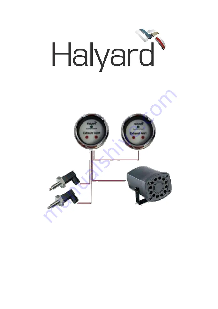
Page 10: ...Exhaust Alert Operating Fitting Instructions 8 HMI 201 01 4 3 Circuit Diagrams Fig 4 Single Engine Single Helm Station Wiring Diagram...
Page 11: ...Exhaust Alert Operating Fitting Instructions 9 HMI 201 01 Fig 5 Twin Engines Single Helm Station Wiring Diagram...
Page 12: ...Exhaust Alert Operating Fitting Instructions 10 HMI 201 01 Fig 6 Single Engine Dual Helm Station Wiring Diagram No 120dB siren...
Page 13: ...Exhaust Alert Operating Fitting Instructions 11 HMI 201 01 Fig 7 Twin Engines Dual Helm Station Wiring Diagram No 120dB siren...
Page 14: ...en the clamping screws 4 6 Sensor Wiring for Twin Engine Installations Prepare the wiring for both sensors as in the Single Engine instructions above Connect the wires from the Port engine sensor to t...
Page 15: ...your connections and compare them with the appropriate wiring diagram Switch ON the engine s ignition power supply Both red and green lights should flash momentarily on the Master gauge and the intern...
Page 16: ...er leaks around the hose connections and the clamps are secure Note any rectification works must only be completed once the engine has been shut down and cooled sufficiently 5 4 Fault Diagnosis Halyar...
Page 17: ...e sensor with 16 metre cable H021249 AS135 Single engine dual station gauge with through hose sensors with 16 metre cable H021250 AS145 Single engine dual station gauge with removable through hose sen...
Page 18: ...Exhaust Alert Operating Fitting Instructions 16 HMI 201 01 Installation Notes Installation Date...
Page 19: ...Exhaust Alert Operating Fitting Instructions 17 HMI 201 01...
Page 20: ...HMI 201 01 Halyard M I Ltd 86 Cobham Rd Ferndown Ind Estate Wimborne BH21 7PQ T 44 1722 710922 E technical halyard eu com W www halyard eu com...