25
j)
Remove the 4 nuts holding the combustion chamber fr
ont
cover in place.
k)
Remove the gas contr
ol valve, fan & burner assembly, by
carefully pulling forward the combustion chamber front and
pivoting the assembly forward, then disengage the gas valve feed
pipe from the casing, by lifting up the assembly. Take care not to
damage the insulation.
l)
The assembly may then be inspected. If the gas valve is to be
replaced refer to section 9.3.
m)
Re-assemble in r
everse order.
6.3
BURNER
Inspect, and if necessar
y clean the main burner ports using a soft
brush or vacuum cleaner. Do not use a wire brush or any
abrasive material.
Inspect the inside of the combustion chamber for debris. If
necessary, clean the inside of the tubes with a soft brush. Do not
brush the insulation at the rear, check the integrity of the
combustion chamber insulation panels, if damaged they will
require replacement.
6.4
IGNITION & DETECTION ELECTRODES
a)
Inspect the ignition and detection electr
odes in situ. If
necessary, clean using a soft brush. If either the electrode or the
ceramic insulation shows signs of damage or wear, replace the
electrode(s) and their gasket.
b)
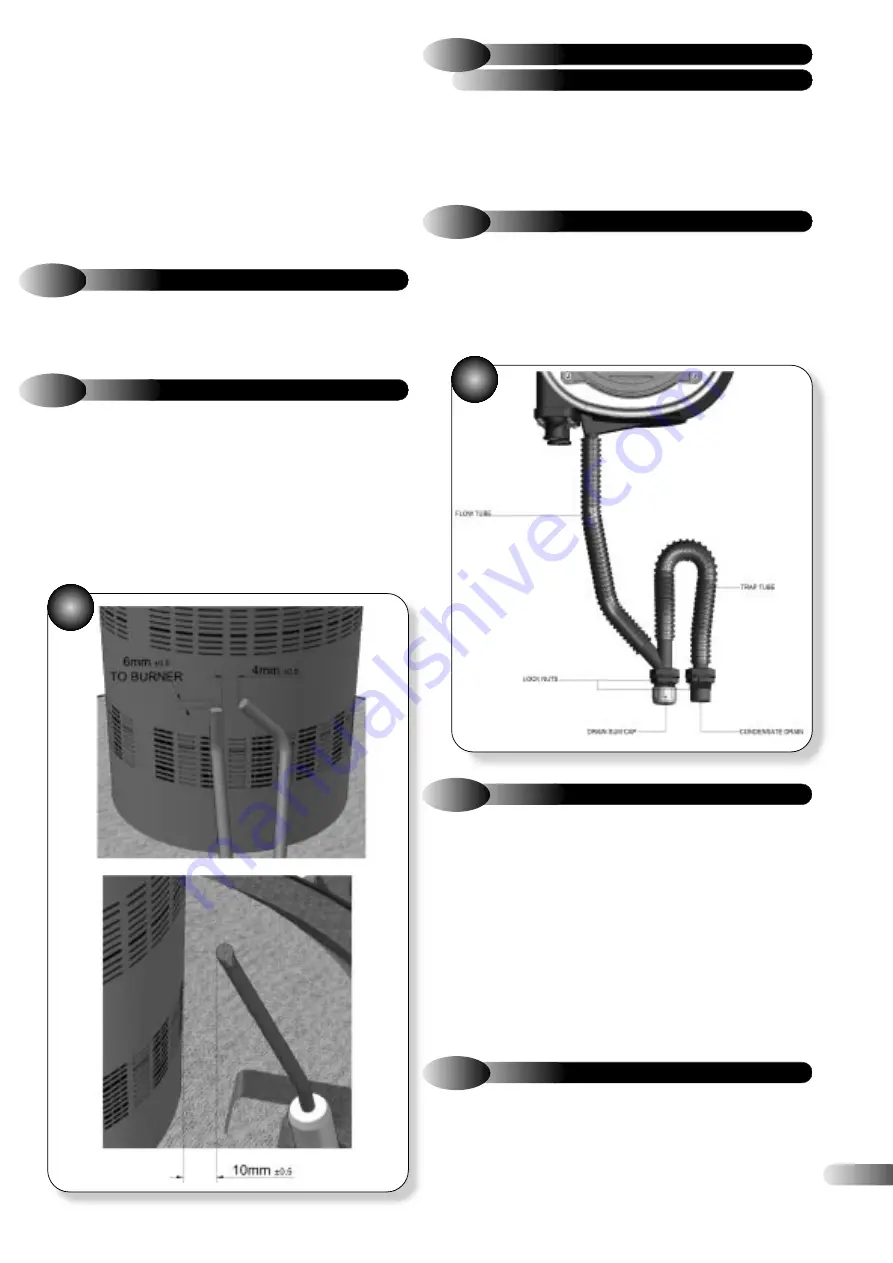
Check that the alignments of the ignition and detection
electrodes are correct. Refer to Figure 29. Adjust by carefully
bending the tip of the electrode rod whilst supporting the base of
the rod. Do not put any pressure on the ceramic insulation.
& HEAT EXCHANGER
6.5
COMBUSTION CHAMBER
The condensate Drain has a r
emovable cap, Figure 30, which
allows the removal of debris that may be caught within it. Place a
bowl under the cap to catch the condensate and remove the cap.
Any debris inside will be expelled at this point. Replace the cap
ensuring a good seal is made. Discard the condensate and debris.
6.6
CONDENSATE DRAIN
30
29
a)
Re-assemble all components in r
everse order.
b)
Check that all joints and seals ar
e correctly fitted.
c)
T
urn on the gas and electricity supply and light the appliance,
as described in section 5.2.
d)
Re-per
form a combustion check, as described in section 6.1.
e)
Check the operation of the appliance in both CH and DHW
modes as applicable.
f)
Remove the manometer and tighten the inlet pr
essure test
point sealing screw.
g)
T
est for gas tightness.
6.7
RE-ASSEMBLY & RE-COMMISSIONING
a)
Ensur
e the fascia panel is placed into the upright position and
secure with the two screws.
b)
Re-fit the fr
ont casing panel.
c)
Retur
n all appliance and external controls (if fitted) to their
original settings.
6.8
FINAL CHECKS


