background image

Ensure compliance with the following instructions prior to beginning work on the Refrigeration unit:

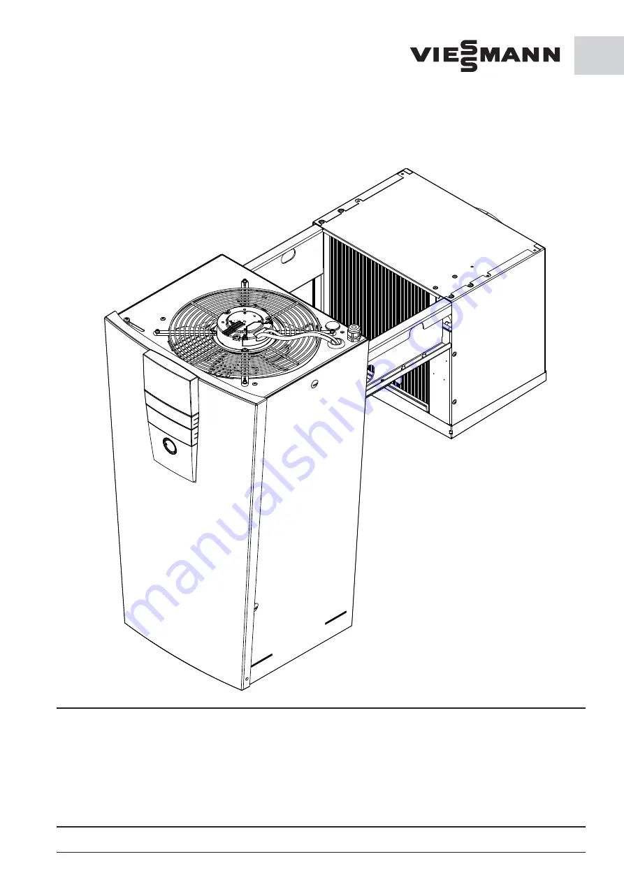
Refrigeration units EVO

-COOL®

Installation and
operating Instructions
6008309-01 GB

General notice (liability): the details of this technical documents serve for description. Consents regarding the availability of certain features or 
regarding a certain purpose always require a special written agreement.

GB

We reserve the right to make technical changes! Status as of 02.15

Page 1

Installation, cleaning maintenance and repair work must be 
performed only by a refrigeration specialist company.

Technical modifi cations and manipulation are prohibited.

Non-compliance will result in forfeiture of all warranty claims.

Work on the Refrigeration unit is authorised only when the mains 
plug has been removed. The Refrigeration unit must be protec-
ted against unauthorized activation by appropriate means
(e.s. warning sign). The directives, VDE 0105 Part 1, for working 
on electrical equipment must be complied with.

Summary of Contents for EVO-COOL CS 1300

Page 1: ...ent GB We reserve the right to make technical changes Status as of 02 15 Page 1 Installation cleaning maintenance and repair work must be performed only by a refrigeration specialist company Technical modifications and manipulation are prohibited Non compliance will result in forfeiture of all warranty claims Work on the Refrigeration unit is authorised only when the mains plug has been removed Th...

Page 2: ...6 3 Defrost water drain 6 4 Preventing excessive defrost water 7 Cooling mode 7 1 How the cooling mode works 7 2 Description of the cooling mode types 8 First steps EVO COOL 9 Operation of the regulation 9 1 Menu Enabling 9 2 Display 9 3 Menu Settings 9 4 Menu Information 9 5 Menu LogBook 9 6 Menu Program 9 7 Menu Change Board 9 8 Menu Data Exchange 9 9 Menu Warnings 10 Bus operation 10 1 Connecti...

Page 3: ...rigera tion circuit has been opened by unauthorised personnel access has been made to the system assembly or the se rial number has been changed or made unrecognisable 2 2 Standards and regulations The EVO COOL refrigeration unit has been built and in spected according to the standards and regulations valid at the time of manufacture It complies with the EMC Directive 2004 108 EC machinery directi...

Page 4: ...be transported in its operating position It must be ensured that the evaporator and condenser units have not been damaged Non compliance will result in forfeiture of the warranty entitlement 2 7 Energy conservation Direct sunlight will raise the consumption of electricity Avoid any unnecessary or too lengthy opening of the door Monitor the storage temperature Regularly clean the Refrigeration unit...

Page 5: ...he time interval for cleaning is dependent on on the am bient conditions Yet at least one maintenance inspection should be performed annually The evaporator unit should be cleaned either with a soft cleaning brush with compressed air or in case of with heavy grease deposits with an industrial cleaner Do not use any sharp or sharp edged object for cleaning It must also be ensured that the thin lame...

Page 6: ...ent can be delivered by us with the respec tive cut outs and bore holes for installation in the cold storage cell Otherwise the required bores holes and cut outs should be made on location by a refrigeration techni cian using installation templates or the dimensional drawings The cutting edges and bore holes must be protected against corrosion with zinc primer paint Attention The electrical power ...

Page 7: ...ical changes Page 43 GB Hang the unit on the storage cell wall while pushing against it from the outside Slide the holding angle against the inside cell wall and tighten it securely with one or two bolts Loosen the locking screws 2 ea on the front access cover Pull the front panel at the bottom a little bit forward then push it upwards and take it off by pulling it forward again Units without a di...

Page 8: ...n hose B and in this pro cess for easier insertion the defrost water drain hose B must be pulled as much in a straight line as possible Guide the defrost water drain hose B through the bore hole G ø 31 mm in the cell wall F from the inside Lubricant can be used if necessary Connect the defrost water drain hose B to the drain port E on the evaporator condensate tray Put the defrost water drain heat...

Page 9: ...ca 10 mm to the back again The defrost water tray is correctly positioned if the side clips P on the defrost water tray are positioned on the metal clips Q Fill out the area above the Refrigeration unit hanging rail with the enclosed Armaflex hoses N as sealing material Seal the rail with sealant if necessary Remount the front access cover securing it to the unit with the enclosed sheet metal scre...

Page 10: ...capacity 230VAC min 0 5 A Connection takes place via the 4 pole socket outlet mounted on the intake side of the evaporator unit In its delivered condition the unit is functionally ready for service without an external door contact switch The door contact switch is not included within the scope of delivery of the unit If a door contact switch is connected to the refrigeration unit the regulation pa...

Page 11: ...by a specialist company in accordance with IEC 364 local regulations and the connection conditions of the respective energy supply company Insert the mains plug into a properly grounded outlet with personal protection measures fault current circuit breaker according to the specification plate Electronic regulation The equipment starts up after self testing the regulation A warning signal sounds up...

Page 12: ...between the 9th and 10th fins and the 1st and 2nd sensor tube at a depth of 34 mm If the sensor is positioned against a tube that is close to the inflow during the defrosting process defrosting does not complete fully The sensor reaches the set defrost temperature prematurely and the control unit terminates the defrosting process The ice is simply melted and sinks to the bottom This results in a b...

Page 13: ...or In other words the ice was formed through a use of energy and likewise melted again Due to the thermody namically induced lack of humidity at the coldest point in the coldroom ice formation cannot be prevented vapour pressure drop but can be minimised The following points should be noted Units in deep freezing rooms should always be coupled with a door contact switch that switches off the evapo...

Page 14: ... points are determined by the desired coldroom temperature and the hysteresis see parameter list in Point 9 3 7 2 Description of the cooling mode types Normal mode The unit is started with Standby No then runs conti nuously The cooling mode is only briefly interrupted by the set defrost cycles Cooling schedule The unit is started with Standby No then only runs at the times approved in the cooling ...

Page 15: ...he function If the button is pushed for a longer period of time the menu selection goes back to the top level 5 With the rotary knob select Enabling and input the numerical sequence 12345 After correct input Welcome appears in the display By pushing the rotary knob further the control goes to the main menu again If the numerical sequence is not correct Login Error please contact your refrigeration...

Page 16: ... code can be used for log in The unit must be released for all operation including Standby mode or temperature changes This provides protection against accidental changes In the original state the passwords for the user 12345 the service 90210 If the access rights are to be modified or for specific users they are inaccessible the passwords need to be modified When losing the passwords their modifi...

Page 17: ...rator fan runs constantly High relative humidity Hysteresis 8K to 1K and 1K to 8K 2K 2K Differntial can be changed between switch on and switch off temperature If the value is negative the refrigeration unit switches off if the cold room temperature has reached the rated temperature value minus the absolute value of the differntial It turns on if the cold room temperature has reached the rated tem...

Page 18: ...ilable When changing the defrost to restart the system is required Defrosting duration 1 min to 60 min 10 min 10 min Time limitation for defrosting in a cycle Defrosting cycle 15 min to 24 h 4 h 2 5 h Defrosting cycle the defrosting process starts at a specified interval Example Every 2h defrosting cycle for a duration of 30 minutes at 2 00 pm defrosting is performed for 30 minutes at 4 00 pm defr...

Page 19: ...before defrosting began in the data logger during defrosting and prevents temperature peaks during defrosting Back Fan Fan type Standard Eco Linear Activation of the fan with 230 V and the control output 0 10 V linear Activation with a straight line through the defined points temperature 5 speed 5 lower point and temperature 1 speed 1 upper point Pr Evap 0 min to 10 min 3 3 Delays the start up of ...

Page 20: ...tional Yes No Yes No Yes No Determination of whether the inlet filter alarm can be evaluated High temp alarm 0 K to 20 K 10 K 10 K The value set added to the cut in temperature is the high alarm set point Low temp alarm 0 K to 20 K 5 K 5 K The value set added to the cut out temperature is the low alarm set point Back Network Attention The settings under this menu item require a restart Use DHCP Ye...

Page 21: ...number of the ref rigeration specialist The service telephone number of the refrigeration specialist can be entered here This is shown on the display alongside the error in the event of a fault Service number Service number of the ref rigeration specialist The service telephone number of the refrigeration specialist can be entered here This is shown on the display alongside the error in the event ...

Page 22: ...t ok Unit sensor VFF condenser sensor ok not ok Condenser sensor HDR high pressure fault ok not ok High pressure NDR low pressure fault ok not ok Low pressure Door door contact switch ok not ok Door alarm Per personnel alarm ok not ok Personnel alarm Fil filter alarm ok not ok Filter alarm Not Emergency mode on ok not ok Once emergency mode is activated the info display can no longer be selected S...

Page 23: ...ctly output onto the display or read via a data carrier The data txt format can be imported into a spreadsheet and evaluated The data in the memory cannot be deleted 9 5 2 Licence release If the data logger is retrospectively ordered the display number must be reported to the factory The display number can be found under Settings Control panel Licence This display number is allocated to a release ...

Page 24: ...eezer Description Temperature Cooling range 5 C to 20 C Setting value 5 C Freezing range 5 C to 25 C Setting value 20 C 5 C 20 C Target temperature input Standby Yes No Switching from standby to cooling Cooling schedule New 99 switching units possible If dates are set in the cooling schedule the unit only runs in the set time frame For con tinual operation the cooling schedule must be deleted Star...

Page 25: ...n Kühlsysteme GmbH www viessmann de kuehlsysteme For the download the e mail address and the company must be specified Copy event file The malfunctions in the last few months can be downloaded to a USB stick The file can be opened with OpenOffice or Microsoft Office Copy temperature file The data from the data logger optional can be downloaded to an USB stick The file can be opened with OpenOffice...

Page 26: ...s type redundant The units run jointly in a coldroom with the same para meters For FS and CS units the model wall hanging unit must be selected see parameter list The model controls the defrost function so that all units are simultaneously defrosted If the option ceiling unit is selected the units defrost at different times For wall hanging units this would lead to ice formation 10 3 Bus operation...

Page 27: ...l circuit diagram Page 66 to 69 After the Time Lighting process main menu Settings sub menu Control Panel the display will go to sleep Thermal detector defective RF breakage short circuit Liquefaction detector not working correctly Log detector not working correctly One or more detec tors are defective Up to 4 thermal detectors PT1000are built into the EVO COOL The display will show which detector...

Page 28: ...anual defrosting and watch whether the evaporator is free of ice after the process is complete If it is not The defrosting cycle is too long and the defrosting time is set too short The defrosting limitation temperature is set too low and prematurely turns off the defrosting process Check whether the door closes correctly and is air tight Adjust if necessary Check whether the pressure compensation...

Page 29: ...Page 65 GB 12 Refrigeration circulation schematic 1 Compressor 2 Pressure line 3 Hot gas line dripping tray 4 Air cooled condenser 5 High pressure switch low pressure switch 6 Inside heat exchanger 7 Collector drier 8 Thermal expansion valve 9 Evaporator 10 Suction line 11 Coldroom 12 Magnetic valve fluid line 13 Magnetic valve hot gas defrosting 14 Schrader test connectors 15 Solenoid valve press...

Page 30: ...rator fan 230V 1 IN NC NO X3D X1 X3F X3E X3H X3G X3C X3B 11 12 14 Alarm contact potential free Door element extract optional X2 L 1 PE N PE L N 13 14 Door contact switch Power board Part number 00173920 M L N PE M M M X3A Attention Before pulling a plug the equipment must be brought to a zero potential status Contacts JST plug A1 A2 B1 Emergency switchoff lower Off Switch for bus address Display a...

Page 31: ...t externally optional A Out GND Data logger detector PT 1000 Room air sensor PT 1000 13 14 Fan speed liquefier A1 A2 A1 A2 A1 A2 A1 A2 A1 A2 A1 A2 A1 A2 A1 A2 A1 A2 A1 A2 Upper display and bus lower bus optional RS 485 via RJ 45 cable Ethernet interface RJ 45 USB port for data exchange Display Part number 00173921 12V X5 11 A1 IN X5 11 A2 1 2 3 1 0 0 0 2 1 0 0 3 0 1 0 4 1 1 0 5 0 0 1 6 1 0 1 7 0 1...

Page 32: ...ating optional L N PE X3D X1 X3C X3B 11 12 14 Power board Part number 00173920 L N PE X3A L N PE N PE L1 L2 L3 F2 Circuit breaker 10A B Direction relay only at Scroll T2 T3 T1 L2 L3 L1 K1 M Electric supply 400V 3 50Hz 16 A K characteristic personal protection measure FI protection switch Switch box for power circuit PE N L1 L2 L3 1 2 3 4 A1 A2 5 6 Attention Before pulling a plug the equipment must...

Page 33: ...hernet interface RJ 45 Power lengths Power board display max 8 m Power board Power board max 15 m IN 12V 12 11 11 ND HD B 12 A C 12 12V X5 11 A1 IN X5 11 A2 IN X5 12 A2 Wiring in the case of HD ND combination switch optional 1 2 3 1 0 0 0 2 1 0 0 3 0 1 0 4 1 1 0 5 0 0 1 6 1 0 1 7 0 1 1 8 1 1 1 DIP switch Address ϑ ϑ ϑ ϑ GEYE green yellow grün gelb BU blue blau BN brown braun BK black schwarz condu...

Page 34: ...6 x 640 x 1239 mm Weight 45 kg 54 kg 58 kg 61 kg 105 kg 107 kg 109 kg Noise level1 24 7 25 4 28 4 27 3 33 4 39 9 37 4 Description FS 900 FS 1200 FS 1400 FS 2000 FS 2500 FS 3000 Coldroom temperature adjustment range 5 C to 25 C Admissible ambient temperature 1 C to 43 C Size 1 2 Cooling capacity 940 W 1250 W 1410 W 1990 W 2490 W 3020 W Refrigerant R404 A Control electronic Voltage Phases Frequency ...

Page 35: ...000 CS 2500 CS 3000 EVO COOL FS 0900 FS 1200 FS 1400 FS 2000 FS 2500 FS 3000 is developed constructed and manufactured according to the EC rules as meutioned above by sole responsibility of Viessmann Kühlsysteme GmbH Schleizer Straße 100 95030 Hof Saale Germany The following national rules and specifications are applied DIN EN 378 DIN EN 50178 DIN EN ISO 12100 DIN EN 55014 1 DIN EN 55014 2 DIN EN ...

Page 36: ...features or regarding a certain purpose always require a special written agreement Right reserved to make technical changes Page 72 GB Viessmann Kühlsysteme GmbH Schleizer Straße 100 95030 Hof Saale Telefon 49 9281 814 0 Telefax 49 9281 814 269 kuehlsysteme viessmann de www viessmann de kuehlsysteme Your responsible refrigeration service ...

Reviews: