background image

6.


Temperature Rise - Supply air temperature minus return air temperature. The temperature rise 
across the furnace (operating at steady state conditions) should be approximately 75

º

F. A higher 

temperature rise would slightly lower the efficiency. The supply air temperature should be 
measured in the supply air trunk-line approximately  12  inches  down  stream  of  the  plenum.                   

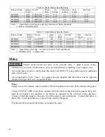
Do not exceed the maximum temperature rise as listed on the furnace nameplate

.  

7.


Check operation of the cad cell relay by removing cad cell wire from external terminal of primary 
safety control to ensure that it goes off on safety. 

8.


Check blower motor amperage under both heating and air conditioning loads and ensure that the 
amperage is less than the full load nameplate amperage of the blower motor. 


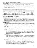
Operating and Maintenance Instructions 

 
                           The  furnace  must  be  installed,  adjusted  and  maintained  only  by  a  qualified  service 
agency annually.  Have your unit inspected, cleaned and adjusted at least once a year to assure proper 
operation.  Do not tamper with the unit or controls.  Incorrect operation of the unit could result in 
severe personal injury and property damage. 

WARNING


Never attempt to use gasoline in the furnace. 


Never store gasoline or other combustible materials near the burner or appliance.  The area around the 
furnace should be kept clear of all combustible materials. 


Never attempt to burn garbage or refuse in the furnace. 


Never attempt to light the furnace by throwing burning material into the furnace. 


Never attempt to use crankcase or waste oil or materials other than the approved fuel oils in this 
furnace. 


Never restrict the air inlet openings to the burner. 


Do not attempt to start the furnace when excess oil has accumulated in the chamber or the furnace is 
full of vapors. 
 

Cleaning 
 

                         Cleaning the heat exchanger must be done yearly by a qualified service technician. 

WARNING

It is important to inspect and clean the heat exchanger once annually or as necessary to remove any 
build up of soot.  A layer of soot on the inside surface of the heat exchanger will result in reduced 
efficiency. 

HB/LB 

1.


Turn off all power to the furnace. 

2.


Remove the upper pouch plate and the flue pipe.  

3.


Lower the combustion baffle  

4.


Using a soft 2" flue brush, cleaning the upper half of each corrugation of any soot buildup.  

5.


Inspect heat exchanger and combustion chamber. 

6.


Place the combustion baffle back to its original position and proceed to clean the lower half 
with the flue brush. 

7.


 Vacuum any loose debris.  

8.


Replace the upper pouch plate and flue pipe. Should any of the gaskets break or otherwise 
not be able to provide an adequate seal, the gasket should be replaced before reassembly. 

9.


Clean and readjust the oil burner as required. 


22 

Summary of Contents for HBD1 15

Page 1: ...n and Operation Instruction Manual Variable Speed 2 Stage ECM Motor Keep these instructions with the furnace at all times for future reference Boyertown Furnace Co PO Box 100 Boyertown PA 19512 610 36...

Page 2: ...our oil fired furnace is designed to burn No 1 and No 2 heating oil only Never use gasoline or a mixture of gasoline and oil Do not store gasoline or other flammable vapors and liquids in the vicinity...

Page 3: ...Venting Chimney Relining Chimney Connector Power Venting Vent Dampers Ventilation and Combustion Air 14 Burner Installation 15 Wiring 16 Power Thermostat Oil Tank and Piping 19 Start Up 20 Start Up Eq...

Page 4: ...24 53 37 1 2 12 10 27 5 8 2 2 22 LB D 115 1 40 00 0 115 0 00 6 80 0 2 0x2 0 150 0 16 00 4 435 4 5 24 42 38 1 2 12 10 20 2 2 22 LB D 85 1 05 00 0 88 00 0 6 82 6 1 6x2 0 117 5 14 00 3 1 2 385 4 2 23 38...

Page 5: ...such installation provided the floor under the furnace is protected in accordance with the requirements of accepted building code practice and NFPA 31 The furnaces shall be permitted to be placed on...

Page 6: ...Rear Sides Above Rear Sides 3 thick masonry wall without ventilated air space N A 12 N A 9 N A 6 N A 5 insulation board over 1 glass fiber or mineral wool batts 12 9 9 6 6 5 4 3 24 gauge sheet metal...

Page 7: ...avoid condensation in the furnace heat exchanger The evaporator coil must be installed at least 6 above the heat exchanger for proper air flow Distances less than 6 will result in decreased air flow...

Page 8: ...Area Sq In 600FPM Area Sq In 800FPM Area Sq In 1000FPM Area Sq In 1200FPM Area Sq In 1600FPM Area Sq In 2000FPM 50 12 100 24 18 14 12 150 36 27 22 18 14 200 48 36 29 24 18 14 250 60 45 36 30 23 18 30...

Page 9: ...mode of operation the blower is to run Air flow rates in the different modes are controled by the setting of the DIP switches Standby Mode The thermostat inputs are being continuously monitored The m...

Page 10: ...hange the air flow settings until the blower has come to a complete stop No change in air flow will occur unless the motor has been allowed to a complete stop See figure below for the location of the...

Page 11: ...5 COOL 6 Y1 7 ADJUST 8 OUT 9 O 10 BK PWM 11 HEAT 12 R 13 EM W2 14 Y Y2 15 G 16 OUT Power connector Signal connector Figure 1 Figure 3Power Connector VENTING Failure to follow all instructions can res...

Page 12: ...cracking from the flue gasses All chimney clean out doors and flue connections must fit tightly so they will seal to avoid air leakage The inside area of the chimney liner should equal at a minimum th...

Page 13: ...tor shall not exceed 10 feet The chimney connector shall be installed so as to minimize the number of elbows and to avoid sharp turns or other construction features that would create excessive resista...

Page 14: ...side wall by using a listed power side wall Venter The vent device must be able to produce a draft of 02 W C over the fire and be equipped with a post purge timer set to a minimum time of 5 minutes T...

Page 15: ...from its shipping carton and inspect thoroughly Verify that the correct burner combination and nozzle is installed in the burner as shipped Read the oil burner manual included in the shipping carton a...

Page 16: ...ments 2 Delavan nozzle 3 Hago nozzle Wiring Electric shock hazard can cause severe personal injury or death if power source including service switch for the furnace is not disconnected before installi...

Page 17: ...17 17...

Page 18: ...ed for AC operation the B terminal is for the reversing valve energized for HP operation When wiring for the first stage cooling choose the appropriate Y1 terminal for the air flow required When insta...

Page 19: ...and across ceiling or floor joists Piping shall be supported and protected from physical damage and where necessary protected against corrosion as per code Piping systems shall be maintained liquid t...

Page 20: ...l residue or foreign materials and that the refractory chamber has not been damaged 4 Check oil burner nozzle to ensure that the right size and type is installed and tight in the adapter See prelimina...

Page 21: ...tings shown in Table 8 thru Table 10 are approximate The burner must be adjusted during actual field installed conditions Failure to do so will result in poor performance and nuisance service calls Af...

Page 22: ...r or appliance The area around the furnace should be kept clear of all combustible materials Never attempt to burn garbage or refuse in the furnace Never attempt to light the furnace by throwing burni...

Page 23: ...ay pattern Perform the combustion checks as per the burner manual and the furnace manual Blowers Direct Drive Clean inspect blower wheel annually Lubricate blower motor as per the motors recommendatio...

Page 24: ...504100 504500 11 1 POUCHPLATE GASKET KIT 489000 489000 12 1 BAFFLE ASSEMBLY KIT 730317K 730317K 13 1 HEAT EXCHANGER KIT 730051K 730061K 14 1 FLUE COVER 740800 740800 15 1 REAR PANEL 504130 504530 16...

Page 25: ...LB REAR AIR BAFFLE 504910 504910 14 1 SEPARATION PLATE 740763 740763 15 1 FLUE EXTENSION PIPE 732690 732691 16 1 REAR PANEL 504030 504430 17 1 FLUE COVER 740800 740800 18 1 DOOR 504040 504440 19 1 BLO...

Page 26: ...es Oil Filter Clean Replace Oil Filter Pump Strainer Clean Clean or Replace Strainer Adjust Pressure Per Set up Label Refer to Burner Manual Pump Pressure Per Set up Label Spark Established Ignition E...

Page 27: ...lts at Furnace 120 Volts at Burner Control Adjust Thermostat Check Supply Fuses and Disconnects Fan and Limit Operational Refer to Burner Manual Burner Off on Safety Refer to Burner Manual No No No No...

Page 28: ...erify Correct Furnace Wiring Repair Wiring Replace Power Cord Yes 24 Volts R C on Terminal Strip Yes Replace Fan Center Relay No Check Wiring Replace Cable Place Jumper on R W 24VAC BetweenPins 1 2 Ch...

Page 29: ...ger Proof of purchase will be required of the original purchaser when the claim is made The purchaser must pay all other costs of warranty services including labor costs involved in diagnostic calls o...

Page 30: ...air flow and ACCA Manual D t Work All ducts sealed and insulated as required Burn Burner Model __________________ Nozzle _______GPH _______Deg _______Type_______ er Operation Burner Pump Pressure ___...

Page 31: ...31...

Page 32: ...Serial Number ________________________ Name of Purchaser _________________________________________________________________________ Purchaser s Address ________________________________________________...

Reviews: