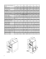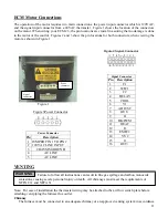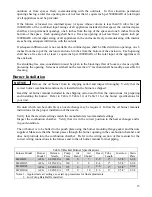
Table 10 Riello Burner Specifications
Furnace Model
Burner
Model
Nozzle Pump
Press.
Air
Setting
1
Turbulator
Setting
Tube
Length
Insertion
LB/HB85
40F3
0.65X60
º
W
160 4.50 0.5 8-7/8”
5-3/4”
LB/HB115
40F3
0.85X60
º
W
160
3.25
2.0
8-7/8”
5-3/4”
LB/HB145
40F3
1.00X60
º
W
160 3.75 3.0 8-7/8”
5-3/4”
LB/HB160
40F5
1.10X60
º
W
160
6.00
3.0
8-7/8”
5-3/4”
Notes: 1. Approximate air settings see start up procedures for final adjustments
2. Burner Amulet Required
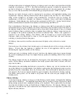
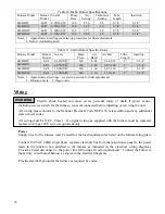
Table 11 Carlin Burner Specifications
Furnace Model
Burner
Model
Nozzle Pump
Press.
Air
Band
1
Air Bar
1
Tube
Length
Insertion
LB/HB85
EZ-1
0.65X70
º
W
2
140 0.65 0.60-0.65 9” 5-3/4”
LB/HB115
EZ-1
0.85X70
º
B
2
140
0.85
0.85-1.00
9”
5-3/4”
LB/HB145
EZ-1
1.00X70
º
B
2
140 1.00 0.85-1.00 9” 5-3/4”
LB/HB160
EZ-1
1.10X70
º
B
2
140
1.10
1.10-1.25
9”
5-3/4”
Notes: 1. Approximate air settings - see start up section for final adjustments
2. Delavan nozzle 3. Hago nozzle
Wiring
Electric shock hazard can cause severe personal injury or death if power source,
including service switch for the furnace, is not disconnected before installing or servicing the unit.
WARNING
All wiring must conform to the National Electrical Code NFPA 70, latest edition and any additional
state or local codes.
All wiring must be N.E.C. Class 1. If original wiring as supplied with the furnace must be replaced,
replace with type 105
º
C wire or equivalent only.
Power
Supply wire for the furnace must be sized for the load requirement as listed on the furnace rating plate.
Connect 120 VAC 60HZ single phase separate electrical line from the main house panel to the power
leads in the junction box attached to the furnace as indicated in the electrical wiring diagrams.
Provide a fused disconnect in the power line following all code requirements. Connect the burner to
the factory wired burner harness as shown in the electrical diagrams.
Provide electrical ground at the furnace as required by codes.
16
Summary of Contents for HBD1 15
Page 17: ...17 17...
Page 31: ...31...


