background image

INSTALLATION

7


8

INSTALLATION

This appliance must be installed by an authorised person in accordance with 
this instruction manual, AS/NZS 5601.1-Gas installations (installation and  
pipe sizing), local gas fitting regulations, local electrical regulations, 
Building Code of Australia and any other government authority. 


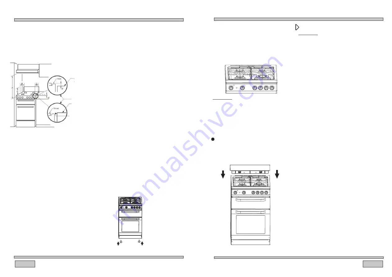
                                                      Overhead clearances-(Measurement A) Range 

                                                      hoods and exhaust fans shall be installed in accordance 
                                                      with the manufacturer’s 
                                                      relevant instructions. However, in no case shall the 

                                                     clearance between the highest part of the hob of the gas 
                                                     cooking appliance and a range hood be less than 600 
                                                     mm or, for an overhead exhaust fan, 750mm 

                                                      Side clearances-(Measurements B,&C) Where B

                                                      any vertical combustible surface, or vertical combustible 
                                                      surface. covered with toughened glass or sheet metal, is

                                                       measured from the periphery of the nearest burner to

                                                      less than 200mm, the surface shall be protected to a
                                                      height C of not less than 150 mm above the hob for the
                                                      full dimension (width or depth) of the cooking surface
                                                      area. Where the gas cooking appliance is fitted with a
                                                      splashback, protection of the rear wall is not required.

                                                     Additional requirements for freestanding and

                                                     elevated gas cooking appliances-(Measurements D


          &E).

Where D, the distance from the periphery of the

                                                     nearest burner to a horizontal combustible surface is 

                                                       than 200mm, then E shall be 10 mm or more, or 

less 

                                                      horizontal surface shall be above the trivet.

the 

                                                        The cooker should stand on a hard,
                                                        even floor (do not put it on a base).

                                                        Before you start using the cooker, it
                                                        should be leveled, which is particularly

                                                         pan. To this purpose, adjustable feet

                                                        can be found upon removing the utility

                                                         important for fat distribution in a frying

                                                         drawer. The adjustment range is +/-5mm.

                                                         If the appliance is used for extended
                                                         periods, it may be necessary to open
                                                         a window in order to boost ventilation.

                                                          The kitchen where the appliance is to

                                                           be installed must be dry and well
                                                           ventilated.

                                                           The room should be equipped with a
                                                           ventilation system that pipes away
                                                           exhaust fumes created during

                                                           consist of a ventilation grid or hood.

                                                           combustion. This system should

                                                           Hoods should be installed according
                                                           to the manufacturer’s instructions.
                                                           The cooker should be placed so as
                                                           to ensure free access to all control

                                                           elements.


Horizontal combustible


   surface below hob

                                                                                                          THE TWO INSETS RELATE TO

                                                                                                          REQUIRENT 3 BELOW


   OR

                                                                                                        Horizontal combustible

                                                                                                         surface above trivet

                                                                                                      NOTE: In this case, any

                                                                                                         vertical combustible

                                                                                                         protected to conform with

                                                                                                        surface needs to be

                                                                                                         requirement 2 below

Gas


connection

Caution

!

The cooker should only be connected to a 
gas supply of the particular type that the 
appliance is manufactured to function with. 

Information about the type of gas that the 

cooker has been adapted to by the factory 

is shown on the rear panel. 

This appliance is suitable for connection with rigid

pipe or flexible hose. The isolating manual shut-off 

valve connection point must be accessible when 
the appliance is installed.


Natural Gas: the supplied regulator must be fitted

 
to the appliance inlet connection. Gas pressure must

be adjusted to 1.0 kPa when approximately 50% 

of the burnersare on high flame, the appliance test  

point is located on the regulator.

LPG: the supplied test point adaptor must be fitted

to the appliance inlet connection. Gas pressure must

be adjusted to 2.75 kPa, the appliance test point


is located on the test point adaptor.

Suitable for connection with a flexible hose assembly.

 
The flexible hose assembly must be certified to

 
AS/NZS 1869 class B or D, be of appropriate internal

diameter for the total gasconsumption, be kept as


short as possible (not exceeding 1200mm), must

not be in contact with the floor or any hot or sharp

surfaces. The hose assembly must not be subject

 
t o strain, abrasion, kinking or deformation.

Gas leakage and operation of the appliance must
be tested by the installer before leaving. Check all


For minor adjustment and fault finding refer to  
page 25 If this appliance cannot be adjusted to
perform correctly. Refer to the warranty card for 

service & parts contact information. Where the 


   Install the cooktop 

Remove the crown caps and burner 
crowns from the oven, and arrange 
them on the cooktop as per the earlier 


diagram entitled. Description of the


Caution

!

The crown cap and burner cap must be tightly 
installed to ensure that the gas flame burns 
as intended. if the flame fails to ignite, it may 
be because these components have been

To fit the rear panel/splashback,slide the


appliance! These components will fit
together neatly when correctly installed.

lugs on the bottom of the panel into the

with screws provided.

matching slots on rear of stove and fix

burner flames are blue in colour, stable and

with no appreciable yellow tipping, carbon
deposition, lifting, floating, lighting back or

completely ignite at both high low flame settings

objectionable odour. Test burners individually and
in combination.

data plate is obscured by cabinetry when the cooker
is in the installed position, place the supplied
duplicate data plate to a suitable adjacent surface
or within the instruction manual for future reference.

incorrectly installed.

Summary of Contents for HOR54B5MCW1

Page 1: ...Cod 0040304164 HOR54B5MCW1 User Manual Free Standing Cooker ...

Page 2: ...ctionality before leaving the factory Caution Do not use this appliance until you have read this instruction manual This appliance is intended for household use only TABLE OF CONTENTS 2 Safety instructions 3 How to save energy 5 Unpacking 5 Disposal of the appliance 5 Description of the appliance 6 Installation 7 Operation 12 Before first use 12 How to use surface burners 12 Oven 14 Cleaning and m...

Page 3: ...ntenna cords e g radio to the gas supply immediately using a cutting off valve In a case of gas escaping from a leaky cylinder and catching fire throw a wet Do not use the damaged cylinder When the cooker is not to be used for several days close the main valve on the gas piping The cooker should not be cleaned using steam equipment Alterations and repairs carried out by an unqualified person are n...

Page 4: ...he direct vicinity of refrigerators freezers Otherwise energy consumption increases unnecessarily Duringtransportation protective packaging was used to protect the appliance against any damage After unpacking please dispose of all elements of packaging in a way that will not cause damage to the environment All materials used for packaging the appliance are environmentally friendly they are 100 rec...

Page 5: ...face needs to be requirement 2 below Gas connection Caution The cooker should only be connected to a gas supply of the particular type that the appliance is manufactured to function with Information about the type of gas that the cooker has been adapted to by the factory is shown on the rear panel This appliance is suitable for connection with rigid pipe or flexible hose The isolating manual shut ...

Page 6: ...are located at the rear of the appliance and must be secured to the wall behind the appliance to prevent accidental tipping tilting The chain length must be as short as practicable to avoid appliance tilting Flexible hose connection In case the appliance is connected by means of a flexible hose the position A of the hose is not permissible In case the connection hose is made of metal position A is...

Page 7: ...er Before first use Remove packaging elements Gently slowly remove labels from the oven door trying not to break the glue tape If any visible trace is left on the glass warm up the oven chamber see below spray the warmed up glass with a glass cleaner and wipe off with a soft cloth Empty the drawer clean off factory preservatives from the oven chamber Take out and wash the oven fittings with warm w...

Page 8: ...shed If the flame goes out repeat the procedure If the burner flame goes out for whatever reason shut the burner off and wait for at least one minute before next attempt Before igniting the burners cover them with appropriate cookware Operation of the burner protection valve Some models are equipped with an automatic system that cuts off gas supply to a burner when the flame has disappeared This s...

Page 9: ... on l Do not line the grill pan with aluminium foil Plates and dishes placed on the floor of the the main oven in use l Do not switch on the grill when using the l grill compartment will be heated when compartment for storage 1 Turn on the oven by rotating the top oven 2 Select the temperature in the oven by Celsius printed on the knob 3 The amber temperature indicator light on the temperature is ...

Page 10: ... THE OVEN Roasting meat Cooking meat weighing over 1 kg in the oven but smaller pieces should be cooked on the gas burners Use heatproof ovenware for roasting with handles that are also resistant to high temperatures When roasting on the drying rack or the grate we recommend that you place a baking tray with a small amount of water on the lowest level of the oven It is advisable to turn the meat o...

Page 11: ...y and replace them carefully to their respective slots Oblique position of components may cause troubled ignition of burners Crown caps are coated with black enamel Discoloration of caps due to high temperatures is inevitable but is has no adversary effect on normal operation of burners Oven The oven should be cleaned after every use When cleaning the oven the lighting should be switched on to ena...

Page 12: ...g in the sink Use a fine steel wool soap pad for removing stubborn stains from the rod shelves and floor of the oven Take care during cleaning not to damage bend or dislodge from the surrounding clips the thermostat sensor which is located at the top right hand side of the oven cleaners or aerosols scouring pads or abrasive CLEANING AND MAINTENANCE 22 21 Removal of the internal glass panel Unscrew...

Page 13: ... Thermostat failure Experts should replace the thermostat Oven is excessively stained Roasting temperature is too high Grid rack and grease tray are incorrectly placed Reduce the roasting temperature Place the grid above the grease tray and insert them both in the guide Liquid or pastry dough is lifted to The appliance is not leveled Level the appliance into horizontal position by setting the adju...

Reviews: