background image

15

15

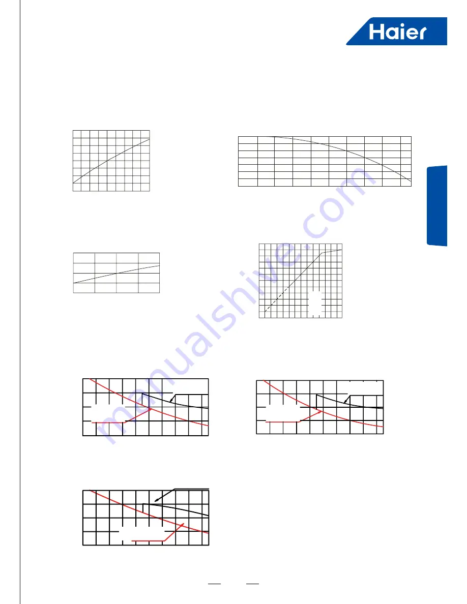
Performance Curves

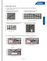
(1) Calculation methed of refrigerating capacity----refrigerating capacity to be


known=refrigerating 

      capacity*(A*B*C*D*E)W

E. Fall of refrigerant pipe of indoor and outdoor unit, capacity compensation value of pipe length

C. Capacity modification value under airflow variation 

     rate of indoor unit group


(only fro duct unit)

A.  Capacity  compensation  value  of  indoor                  

     air wet-bulb temperature condition

B. Capacity compensation value of outdoor   
     air dry-bulb temperature condition

D. Capacity compensation suitable for 
     total capability of indoor unit group

6. Performance Curves

1.2

1.1

1.0

0.9

0.8

15

20

24

Indoor air dry-bulb temperature (°C


)

Capacity modification value

1.2

1.1

1.0

0.9

Outdoor air wet-bulb temperature (°C


)

Capacity modification value

-5

20

0

25

5

30

10

35

15

40 43

1.1

1.0

0.9

80

90

100

110

120

Airflow variation rate (%)

Capacity modification value

120

100

100 120 130

80

60

40

20

20 40 60 80

0

Total capacity of indoor unit group (%)

Standard

capacity

liquid pipe

: φ12.7

gasp ipe

:φ31.8

Single-way pipe length m

)

AV12NMSETA

)

Capacity modification value

1.00

0.95

0.90

0.85

0.80

100 120 140 160 180

20 40

60 80

0

Liquid pipe: φ12.7

Gas pipe : φ25.4

Liquid pipe: φ15.88

Gas pipe : φ28.58

Single-way pipe length (m)

AV12NMSETA

Capacity modification value

1.00

0.95

0.90

0.85

0.80

100 120 140 160 180

20 40

60 80

0

Liquid pipe: φ12.7

Gas pipe : φ22.22

Liquid pipe: φ9.52

Gas pipe : φ19.05

Single-way pipe length (m)

AV08NMSETA

Liquid pipe: φ12.7

Gas pipe : φ25.4

Liquid pipe: φ9.52

Gas pipe : φ22.22

Capacity modification value

1.00

0.95

0.90

0.85

0.80

100 120 140 160 180

20 40

60 80

0

Single-way pipe length (m)

AV10NMSETA

Summary of Contents for AV08NMSETA

Page 1: ...SYJS 11 2016 REV A Edition 2016 11 Service Manual MRV SII ...

Page 2: ... 6 3 Refrigerant Circuit 12 4 Dimension 13 5 Wiring Diagram 14 6 Performance Curves 15 7 Noise Level 17 8 Outdoor Installation 18 9 Electric Installation 37 10 Trial Operation 40 11 Dip Switch Setting 50 12 Digital Tube Display 53 13 Failure Code 54 14 Troubleshooting 58 APPENDIX 76 ...

Page 3: ... AD182MHERA AD242MHERA AD282MHERA AD302MHERA AD382MHERA AD482MHERA AD722MHERA AD962MHERA CONVERTlBLE TYPE AC092MCERA AC122MCERA AC162MCERA AC182MCERA AC242MCERA AC282MFERA AC302MFERA AC382MFERA AC482MFERA SLIM LOW ESP DUCT AD072MSERA AD092MSERA AD122MSERA AD162MSERA AD182MSERA AD242MSERA BUILIT IN FLOOR STANDING AE072MLERA AE092MLERA AE122MLERA AE162MLERA AE182MLERA AE242MLERA 2 WAY CASSETTE 1055I...

Page 4: ...with AC motor and power input largely decrease big diameter fan 570mm big diameter fan more big air flow and more higher efficiency AC motor efficiency DC motor efficiency 100 80 60 40 20 0 100 80 60 40 20 0 0 200 400 600 800 1000 0 200 400 600 800 1000 45 85 95 87 5 35 25 efficiency 45 enhanced Ø570mm fan DC motor control efficiency increase 45 comparing with AC motor and power input largely decr...

Page 5: ...onance structure ensure smooth running of the motor reduce operating noise Big diameter fan design according to aviation quieter principle DC motor High reliability Refrigerant automatically reclaim technology Set refrigerant automatically reclaim through dip switch the refrigerant in indoor and pipe can be automatically return to outdoor convenient in maintenance and reducing waste of refrigerant...

Page 6: ...mpressor and more precise control the temperature can be control 0 5 C Reducing the module temperature Easy installation Compact side discharge design Big capacity small floor area Small floor area only 0 42m 43 floor area can be reduced Compact side discharge design No need additional ventilation hood comparing with top discharge unit 0 745m2 0 42m2 43 reduced 188mm height reduced 0 8m 1 8m 0 77m...

Page 7: ... observed directly by opening the protective cover in case of maintenance to avoid removing the repair board Easy maintenance for control The control box is in front reserving space Parameter display Cover AC FAN Control PCB Main PCB Traditional products need to open the front panel or top control box cover for maintenance DC FAN Control PCB Maintenance from the top Hinge design Difficult to maint...

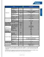
Page 8: ...sor Brand MITSUBISHI ELECTRIC Model LNB53FCAMC Type Rotary Compressor quantity 1 INV Capacity W 16860 Power Input W 5200 Rated current RLA A 15 4 Speed rps 60 0 Crankcase Heater W 60 0 Refrigerant oil brand IDEMITSUKOSAN CO LTD Refrigerant oil type FV50S Refrigerant oil charge ml 1700 0 Outdoor fan motor Brand NIDEC TECHNO Model SIC 81FW F1145 1 Voltage 310 0 IP Class IP42 Type DC Insulation class...

Page 9: ...kg 168 Gross weight kg 183 Refrigerant Type R410A Charged volume kg 7 4 Throttle type EXV Design pressure MPa 4 15 Refrigerant piping Liquid pipe mm 9 52 Gas pipe mm 19 05 Total pipe lenth m 300 Max pipe length Equivalent Actual m 175 150 Max Diff indoor outdoor unit m 50 Outdoor higher than indoor 40 Indoor higher than outdoor Max Diff indoor indoor unit m 15 Connectable indoor unit ratio 50 130 ...

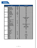
Page 10: ...d MITSUBISHI ELECTRIC Model LNB53FCAMC Type Rotary Compressor quantity 1 INV Capacity W 16860 Power Input W 5200 Rated current RLA A 15 4 Speed rps 60 0 Crankcase Heater W 60 0 Refrigerant oil brand IDEMITSUKOSAN CO LTD Refrigerant oil type FV50S Refrigerant oil charge ml 1700 0 Outdoor fan motor Brand NIDEC TECHNO Model SIC 81FW F1145 1 Voltage 310 0 IP Class IP42 Type DC Insulation class E Safe ...

Page 11: ...ating type Powder coating Salt spray test duration Hour 72 Sheet metal material Hot zinc plate Sheet metal thickness mm 1 0 Control panel enclosure IP class Standard IP24 Outdoor air flow m3 h 10000 Outdoor sound level sound pressure level dB A 58 Outdoor sound level sound power level dB A 69 Outdoor unit Dimension W H D mm 1050 400 1636 Packing W H D mm 1150 510 1790 Net weight kg 168 Gross weigh...

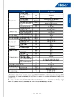
Page 12: ...and MITSUBISHI ELECTRIC Model LNB53FCAMC Type Rotary Compressor quantity 1 INV Capacity W 16860 Power input W 5200 Rated current RLA A 15 4 Speed rps 60 0 Crankcase heater W 60 0 Refrigerant oil brand IDEMITSUKOSAN CO LTD Refrigerant oil type FV50S Refrigerant oil charge ml 1700 0 Outdoor fan motor Brand NIDEC TECHNO Model SIC 81FW F1145 1 Voltage 310 0 IP class IP42 Type DC Insulation class E Saf...

Page 13: ...183 Refrigerant Type R410A Charged volume kg 7 4 Throttle type EXV Design pressure MPa 4 15 Refrigerant piping Liquid pipe mm 12 7 Gas pipe mm 25 4 Total pipe lenth m 300 Max pipe length Equivalent Actual m 175 150 Max Diff indoor outdoor unit m 50 Outdoor higher than indoor 40 Indoor higher than outdoor Max Diff indoor indoor unit m 15 Connectable indoor unit ratio 50 130 Maximum indoor units Pie...

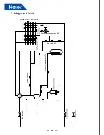
Page 14: ...mbient temp sensor Ta Electronic expansion valve PMV Spray valve SV2 Suction temperature sensor Ts Unload valve SV1 Discharging temperature sensor Td Gas pipe valve Oil temperature sensor Toil Ambient temp sensor Ta Gas pipe valve ...

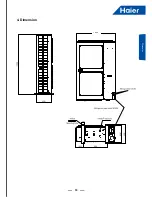
Page 15: ...13 13 Dimension 4 Dimension 1050 D ...

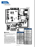
Page 16: ...ding valve SV2 Spray valve 4WV 4 way valve CA Capacitor ACFAN2 AC fan motor DCFAN1 DC fan motor HPS High pressure switch Td Discharging temp sensor Te1 2 Defrost temperature sensor Symbol Signification Ts Suction temperature sensor Ta Ambient temperature sensor Pd High pressure sensor Ps Low pressure sensor Toil Oil temperature sensor EEV Electronic expansion valve Tfin IPM temperature sensor CB1 ...

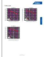
Page 17: ...r wet bulb temperature C Capacity modification value 5 20 0 25 5 30 10 35 15 40 43 1 1 1 0 0 9 80 90 100 110 120 Airflow variation rate Capacity modification value 120 100 100 120 130 80 60 40 20 20 40 60 80 0 Total capacity of indoor unit group Standard capacity liquid pipe φ12 7 gasp ipe φ31 8 Single way pipe length m AV12NMSETA Capacity modification value 1 00 0 95 0 90 0 85 0 80 100 120 140 16...

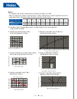
Page 18: ...t group only fro duct unit B Capacity compensation value of outdoor air wet bulb temperature condition D Capacity compensation suitable for total capability of indoor unit group E Capacity compensation value of pipe length between outdoors F Capacity compensation value for defrost capability of outdoor heat exchanger 1 2 1 2 1 1 1 0 0 9 0 8 15 20 24 Indoor air dry bulb temperature 1 1 1 0 0 7 0 9 ...

Page 19: ...er frequency Hz AV10NMSETA Octave band sound pressure level dB A Limit of audible continuous noise 70 60 50 40 30 20 10 63 125 250 500 1000 2000 4000 8000 NC 20 NC 30 NC 40 NC 50 NC 60 Octave band center frequency Hz H AV12NMSETA Octave band sound pressure level dB A Limit of audible continuous noise 70 60 50 40 30 20 10 63 125 250 500 1000 2000 4000 8000 NC 20 NC 30 NC 40 NC 50 NC 60 Octave band ...

Page 20: ...t or fire When installing or moving the unit the refrigerant system should be vacuumed and recharged with R410A refrigerant If any other gas enters the system it may lead to abnormal high pressure which may cause damage or injury Please use the proper manifolds or branches during the system installation The wrong parts may cause refrigerant leakage Keep the drain pipe away from toxic gas vents to ...

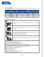
Page 21: ...5 Flare tool 6 Copper pipe gauge for adjusting projecting margin 7 Vacuum pump fitting Vacuum pump must be equipped with check valve 8 Leakage detector Only Helium detector permitted When charging refrigerant the refrigerant must be in liquid state from the tank To prevent EMC interference on other appliances please keep indoor unit outdoor unit power cable and connecting wire at least 1m away fro...

Page 22: ...ion No obstacle at the air inlet outlet And no strong wind blows the unit The installation space refers to the latter info The unit should be installed at the strong enough place Or it will cause vibration and noise The place where the water can flow fluently The place where no other heat source will affect the unit Pay attention to the snow against clogging the outdoor In installation install the...

Page 23: ...el to rise slowly Do not remove the packaging When hoisting do not have to tie up the elevator to the unit hits on the packaging and the outside wrapping When hoisting exterior must use the suitable protection Handling Before the installation outdoor do not deposit any material otherwise likely has the fire or the accident When handling unit please operate as shown in the following figure and note...

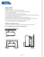
Page 24: ...ate an electricity box and keep off electromagnetic wave radiation possibly at least more than 3 meters When ice snow overlay area installs outdoor unit please add to defend snow cover Outdoor unit installed in the shade avoiding direct sunlight or high temperature heat sources of radiation Do not install in dusty or polluted place to prevent outdoor unit heat exchanger jam The outdoor unit should...

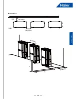
Page 25: ...23 23 Outdoor Installation Multi Outdoor Min300mm Min300mm Min360mm Min300mm Inlet Outlet h A ...

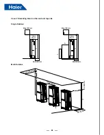
Page 26: ...24 24 Case 2 Stumbling block on the inlet and top side Single Outdoor Multi Outdoor Max300mm Min360mm Min300mm Min500mm H Max300mm Max300mm Min 500 mm Min360mm Min360mm L H H A Min 500 mm ...

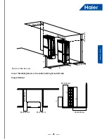
Page 27: ...door Installation Case 3 Stumbling block on the outlet both right and left side Single Outdoor Max300mm Min300mm Min150mm Min300mm Min1000mm Min1000mm Min360mm Min360mm Min500mm H H A L h Not more than two sets ...

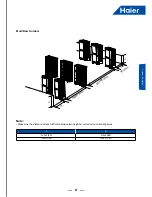
Page 28: ...in300mm Min360mm Min1000mm Min1000mm H h If h H please set the outdoor on the foundation to make sure H h H The height of outdoor and foundation h A 0 h 1 2H Over 600 1 2H h H Over 1400 Note Avoid making air short cycle in any case ...

Page 29: ...Outdoor Installation Multi Row Outdoor Min 360mm Min600mm Min3000mm A h h Note Make sure the distance at least 300mm between two neighbor units and no stumbling block h A 0 h 1 2H Over 600 1 2H h H Over 1400 ...

Page 30: ...he nitrogen should flow under the pressure of about 0 5Mpa and when charging the nitrogen stop up the end of the pipe by hand to enhance the pressure in the pipe then loose the hand meanwhile stop up the other end The piping installation should be executed after the stop valves are closed When welding the valve and the pipe cool down the valve with wet towel When the connection pipe and the branch...

Page 31: ...capacity Indoor rated capacity x100w Gas pipe Liquid pipe Note 22 28 9 52 6 35 AS07 092MGERA gas pipe should be 12 7 AS182MGERA gas liquid pipe should be 15 88 9 52 36 56 12 7 6 35 71 140 15 88 9 52 226 300 25 4 9 52 450 600 28 58 12 7 1 When pipe length between indoor nearest branch pipe 15m adjust in accordance with following criteria If indoor rated capacity 5 6kW change gas liquid pipe diamete...

Page 32: ...ce b diameter to be the same as pipe c Enlarge main pipe c diameter to be the same as pipe b 3 If pipe b diameter smaller than pipe a the pipe b diameter must be enlarged x 16 8kw 15 88 9 52 16 8kw x 22 4kw 19 05 9 52 22 4kw x 33kw 22 22 9 52 33kw x 47kw 28 58 12 7 47kw x 71kw 28 58 15 88 71kw x 104kw 31 8 19 05 104kw x 154kw 38 1 19 05 154kw x 182kw 41 3 19 05 x 182kw 44 5 22 22 3 Main pipe c bet...

Page 33: ...Pipe in above figure Single way total pipe length total liquid pipe length 300m L1 L2 L3 L4 L5 L6 L7 L8 L9 L 10 L11 Single way max pipe length max length between outdoor indoor actual equivalent length 150m 175m L1 L3 L10 L11 Pipe length after first branch pipe length between first branch farthest indoor 40m L1 L10 L11 Main pipe actual length length between first gather pipe first branch pipe 110m...

Page 34: ...use of using a reduser pipe Ø9 52 AV12NMSETA Ø25 4 Ø12 7 Flared joint B Indoor Unit Model Capacity Gas pipe side Liquid pipe side Diameter mm Connecting method Diameter mm Connecting method 07 Ø9 52 Flared Ø6 35 Flared 09 Ø9 52 Ø6 35 12 Ø12 7 Ø6 35 16 Ø12 7 Ø6 35 18 Ø12 7 Ø6 35 24 Ø15 88 Ø9 52 28 Ø15 88 Ø9 52 30 Ø15 88 Ø9 52 38 Ø15 88 Ø9 52 48 Ø15 88 Ø9 52 72 Ø25 4 Braze Ø9 52 96 Ø25 4 Ø9 52 Note ...

Page 35: ...ase don t let the pipe and the parts in the unit collide each other When connecting the pipes close the valves fully Protect the pipe end against the water impurity into the pipes welding after being flat or being sealed with adhesive tape Bend the pipe as large semi diameter as possible over 4 times of the pipe diameter The connection between outdoor liquid pipe and the distributing pipe is flare...

Page 36: ...g sealed with adhesive tape The refrigerant pipe should be clean The nitrogen should flow under the pressure of about 0 5Mpa and when charging the nitrogen stop up the end of the pipe by hand to enhance the pressure in the pipe then loose the hand meanwhile stop up the other end When connecting the pipes close the valves fully When welding the valve and the pipes use the wet cloth to cool down the...

Page 37: ...ot go down the test is passed Meanwhile when the temp changes for 1degree pressure will change 0 01MPa as well Correct the pressure e After confirmation of a d if pressure goes down there is leakage Check the brazing position flared position by laying on the soap Modify the leakage point and take another leakage test After leakage test must execute the evacuation C Evacuation Evacuate at the check...

Page 38: ...essor will occur failure the charging must be finished within 30 minutes especially when the unit is running meanwhile charging the refrigerant The unit is charged only part of the refrigerant at the factory also need additional refrigerant at the installation site W1 Refrigerant charging volume to outdoor unit at factory W2 Refrigerant charging volume to outdoor unit on site W3 Refrigerant chargi...

Page 39: ...ap then be wrapped with adhesive tape The connection wire can not be put together with the heat insulation material and should be far at least 20cm Fix the refrigerant pipe In operation the pipe will vibrate and expand or shrink If not being fixed the refrigerant will focus on one part to cause the broken pipe To prevent the central stress fix the pipe for every 2 3m Refrigerant record form Model ...

Page 40: ...lel through 2 non polar wires Three wiring methods between wired controller and indoor unit A 1 to multi group control one wired controller controls 2 16 indoors as shown in above figure indoor 1 indoor 5 indoor 5 is wired control master unit the others are wired control slave units Wired controller and the master indoor directly connected to wired controller is connected by 3 polar wires the othe...

Page 41: ...Hz Power source 3N 380 400V 50 60Hz Power source 3N 380 400V 50 60Hz Power source 3N 380 400V 50 60Hz Ground Fault Interruptor Circuit Breaker Ground Fault Interruptor Circuit Breaker Ground Fault Interruptor Circuit Breaker Ground Fault Interruptor Circuit Breaker Ground Fault Interruptor Circuit Breaker Ground Fault Interruptor Circuit Breaker Outdoor 1 Indoor 1 Indoor 2 Indoor 3 Outdoor 2 Outdo...

Page 42: ...th cannot exceed 600m Item Indoor total current A Power cable section mm Wire length m Rated current of overcurrent breaker A Rated current of residual circuit breaker A Ground fault interruptor mA Response time S Communication wire section Outdoor indoor mm Indoor indoor mm 10 2 20 20 20A 30mA below 0 1s 2 core 0 75 2 0mm shielded wire 10 and 15 3 5 25 30 30A 30mA below 0 1s 15 and 22 5 5 30 40 4...

Page 43: ...he range the protection device will act The relative humidity should be lower than 80 If the unit runs at the humidity over 80 for a long period the dew on the unit will drop down and the vapour will be blowed from air outlet Protection device such as high pressure switch High pressure switch is the device which can stop the unit automatically when the unit runs abnormally When the high pressure s...

Page 44: ...de oil equalization pipe If operating the unit without opening the valves compressor failure will occur Confirm all indoor units being electrified If not water leakage will occur Measure the system pressure with pressure gauge at the same time operate the unit Trial operation In trial operation refer to the information of performance section When the unit can not start up at the room temperature m...

Page 45: ...eing electrified measure the resistors among live wire neutral wire and earthing point on the terminal block with the 500V ohmmeter The resistor must be over 1 M Ohm 3 2 Outdoor unit confirmation NO Inspection items Results 1 If outdoor unit is in good condition and if the electric box is fixed firmly 2 If outdoor wiring is correct If the wires are broken 3 If the dip switch of outdoor unit is set...

Page 46: ...e the phase sequence but the shielded wire is needed The shielded layer among indoors must be continuous The communication wire of the whole system must be earthed at the farthest shielded wires of indoor and outdoor 6 If the communication wire between indoor and wired controller complies with requirement and A B C must be corresponding or the wired controller will be abnormal 7 The distance betwe...

Page 47: ...hes 2 If indoor communication indicator flashes 3 Check the indoor running parameters are correct after outdoor is connected the testing board and the testing software such as the sensor characteristic the EEV open angle etc If RUN LED on wired controller is light If STANDBY on wired controller is light If the failure code is displayed on wired controller Refer to the troubleshooting and diagnosis...

Page 48: ...tdoor temp pipe length refrigerant charging amount indoor capacity compressor running frequency outdoor fan operation and if compressor sounds abnormal noise If the louver direction Temp difference between air outlet and air inlet is good If running current is in the range of rated current 15 At the max Frequency If running voltage is proper 380V 10 Make all indoors running simultaneously If blowi...

Page 49: ...frigerant charging amount indoor capacity compressor running frequency outdoor fan operation and if compressor sounds abnormal noise If the louver direction Temp difference between air outlet and air inlet is good If running current is in the range of rated current 15 At the max Frequency If running voltage is proper 380V 10 Make all indoors running simultaneously If blowing out hot air If the ven...

Page 50: ...een L and N on indoor terminal block is AC 220V Check indoor power cable If indoor fuse is normal Connect CN23 Check the abnormal feason 1 Indoor transformer abnormal 2 Indoor PCB abnormal 1 Indoor transformer abnormal 2 Wiring of indoor PCB is damaged or the port is not inserted well Heating mode in priority the non prior mode cooling and the mode are different Indoor groups faulty 1 Indoor PCB a...

Page 51: ...g If voltage among B C on wired controller is AC 15V If voltage between B and C on indoor terminal block is 15V 1 Indoor PCB abnormal 2 Wiring of indoor PCB is damaged or the port is not inserted well Fan capacitor abnormal If fan motor rotation direction is correct If the indoor motor runs 1 Indoor PCB abnormal 2 Wiring of indoor PCB is damaged or the port is not inserted well If capacitor capaci...

Page 52: ...re 2 0 3 5MPa Indoor 18 32 C Outdoor 25 35 C Low pressure 0 6 1 0MPa Heating at max frequency High pressure 2 2 2 8MPa Indoor 15 25 C Outdoor 5 10 C Low pressure 0 3 0 8MPa The above value is measured after running for 15 minutes ambient temp is DB C High low pressure changing trend due to the running condition Cooling heating Indoor temp goes up high low pressure goes up Indoor temp goes down hig...

Page 53: ...51 51 Dip Switch Setting 11 Dip Switch Setting Outdoor PCB photo BM2 SW1 SW2 SW3 SW4 LED3 LED1 BM1 LED2 LED4 ...

Page 54: ...temp reaches the target value Power on then OFF ON Unit shall startup after 2 hours preheat or oil temp reaches the target value note here the target value is lower than the target value when the BM1 2 on OFF position BM1_3 Compressor brand OFF Default MHI compressor BM1_4 BM1_5 Piping length selection Single way total pipe length 4 5 Piping length selection OFF OFF Medium piping length 100m L 200...

Page 55: ...mp selection OFF Heat pump default ON Cooling only BM2_2 BM2_3 Outdoor capacity selection 2 3 Outdoor capacity selection OFF OFF 8HP AV08NMSETA ON OFF 10HP AV10NMSETA ON ON 12HP AV12NMSETA BM2_4 Heat reservation module selection OFF Default no heat reservation module note forbid changing BM2_5 Indoor and outdoor high drop selection OFF No high drop default ON High drop BM2_6 Communication protocol...
Page 56: ... heating display HHH otherwise 4 0 F Display indoor failure code 5 0 F Indoor capacity 7 0 F Indoor PMV valve open range 9 0 F Indoor Ta ambient temperature A 0 F Indoor TC1 gas temperature B 0 F Indoor TC2 liquid temperature C 0 F Indoor units fan speed of indoor units 0 OFF 1 Low 2 med 3 high E 0 F Forced cooling press start for 5sec for cooling operation of indoor units and press stop for 5sec ...

Page 57: ...nutes AD value is below 11 open circuit or over 1012 short circuit for 60seconds in course of startup defrosting and within 3 minutes after defrosting no alarm Resumable 24 24 Oil temp sensor Toil failure AD value is below 11 open circuit or over 1012 short circuit for 60seconds if Ta 10degree or ET 10degree within 5 minutes no alarm Resumable 26 26 0 Indoor communication failureI For continuous 2...

Page 58: ...ditions can be met for continuous 10 seconds that is conversing successfully 1 this outdoor compressor is running normally 2 Pd Ps 0 6MPa Otherwise the system alarms reversing failure Once confirmation un resumable 36 36 Oil temp too low protection Toil In normal operation if Td CT 6 Cfor continuous 5 minutes the unit stops and alarms 2 minutes and 50 seconds later resume automatically If it occur...

Page 59: ...rm the failure After fixed frequency compressor alarms inverter compressor will continue to run If fixed frequency compressor has been locked for 3 times the unit will stop and alarm Once confirmation un resumable 46 46 Communication with inverter board failure No communication within 30 seconds continuously Resumable 71 71 DC motor blocked Running at speed below 20rpm for 30s or at speed of 70 lo...

Page 60: ...an hour confirm failure once confirmation un resumable 118 118 Compressor startup failure The sensor used for current detecting of transducer is abnormal disconnected or incorrectly connection 120 120 Power supply of transducer abnormal Power supply of transducer is broken down instantly 121 121 Power supply of inverter board is abnormal Power supply of inverter board is broken down instantly 3 ti...

Page 61: ... is faulty if yes replace it If sensor resistor characteristic is proper If sensor resistor characteristic is proper Reconnect Reconnect Replace sensor Replace sensor Charge refrigerant Replace connecting board No No No No No Yes Yes Yes Yes Yes 14 Troubleshooting 20 24 Temperature sensor failure 27 Protection of oil temperature too high ...

Page 62: ...ailure disappears after changing indoor PCB If there is noise source Check outdoor PCB if faulty replace it If communication wire is separate from high voltage wire on layout Modify the communication wire Modify the port Connect power source Change communication wiring type Shut off power supply and outdoor searches for indoors again Eliminate noise source No No No No No No No No Yes Yes Yes Yes Y...

Page 63: ...r by multimeter If voltage between white terminal and black terminal is 0 5V 3 5V when testing pressure sensor by multimeter Replace connecting board Reconnect Reconnect Replace PCB Replace pressure sensor No No No No Yes Yes Yes Yes If the EEPROM is fixed well Replace EEPROM 28 29 High low pressure sensor failure 33 Outdoor EEPROM failure ...

Page 64: ...clogged Make pressure switch terminal on connecting board in short circuit check if failure exists still If sensor resistor characteristic is proper If sensor terminal is fixed well If the system is lack of refrigerant Replace connecting board Replace pressure switch and measure again Re connect Replace pressure switch Check the piping system Replace connecting board Reconnect Replace sensor Charg...

Page 65: ...ct Check if SV1 leaks Replace connecting board Check compressor Measure if CN49 voltage on connecting board is 220VAC after 4 way valve reversing condition is met If there is air noise after 4 way valve reverses and if the temp of connection pipes with 4 way valve is normal If compressor running current is normal No No No No No Yes Yes Yes Yes 35 4 way valve reversing failure ...

Page 66: ...s fixed well Check if refrigerant is too much In cooling mode when the indoor unit off if the EEV can t completely close Fix again or replace the sensor Reconnect Replace or adjustment the indoor unit EEV Recharge refrigerant Yes No No No Yes Yes Yes 36 Protection of oil temperature too low ...

Page 67: ...al pressure is in conformance with the measured data by sensor Check if terminal of electronic expansion valve coil is fixed well Check if piping system is clogged Check if system is lack of refrigerant Check if stop valve is open fully Replace pressure sensor Open stop valve Recharge refrigerant Re connect the terminals Clear the piping No No No No Yes Yes Yes Yes Yes 39 0 39 1 Low pressure too l...

Page 68: ...r runs normally If stop valve opens fully If in heating indoor fan motor runs normally and if filter is clogged Check if piping system is clogged No No No No Yes Yes Yes Yes Yes Replace pressure sensor Open stop valve Check fan motor Check indoor Clear the piping 40 High pressure protection ...

Page 69: ...sensor is fixed well Check if refrigerant is too much In cooling mode when the indoor unit off if the EEV can t completely close No No No Yes Yes Yes Yes Re connect Replace module Replace wire Replace connecting board In cooling mode when the indoor unit off if the EEV can t completely close Measure if voltage of CN28 on connecting board changes by multimeter Check if communication wire between co...

Page 70: ...viously fiction Forced the fan in low speed measure if it has alternating voltage between FG and GND Check the motor and PCB connection is well Replace fan motor Re connect Replace the motor Replace the outdoor PCB No No No Yes Yes Yes 71 DC motor blocked ...

Page 71: ...re connected oppositely If 4 way valve is interconnected Measure if there is voltage U V W of compressor by multimeter and if it is normal Replace inverter compressor Re connect Correct compressor wire Correct compressor wire Replace 4 way valve Replace inverter module No No No No No Yes Yes Yes Yes 75 No pressure drop between high pressure and low one ...

Page 72: ...Remove the failure Solve the failures due to relative information If power module is normal Check if wire of electric box is correct and if compressor wire is fixed well If there are the other failure recently such as 112 113 114 If compressor is normal compressor coil resistor insulation No No No No No Yes Yes Yes Yes Yes 110 Power module overcurrent ...

Page 73: ... normal If compressor is normal compressor coil resistor insulation Compressor load too much check the reason Check the temperature sensor characteristic is correct Check the radiator is blocked If screw of module is fixed well and if radiating silica gel is daubed enough and evenly if there is no dirt on radiator Improve the running environment of outdoor unit Fix it well and daub gel again clean...

Page 74: ...3 Protection of overload 114 Voltage too low of DC bus line of transducer Check if voltage of power supply is normal Measure if DC bus line voltage between P and N of module is less than 375V Circuit of DC bus line voltage on inverter control board abnormal replace inverter control board If AC contactor or relay acts well Improve power supply circuit Adjust or replace relay Correct the wiring due ...

Page 75: ...ct Improve power supply circuit Correct the wiring due to diagram Circuit of DC bus line voltage on inverter control board abnormal replace inverter control board Yes Yes Yes No No No Check if wire between control PCB and inverter board is abnormal If inverter module board is abnormal Replace main control board Adjust communication wire Check if communication circuit of main control PCB is abnorma...

Page 76: ...ce power module If compressor is normal compressor coil resistor insulation Yes Yes Yes Yes No No No No 117 Transducer over current software protection 118 Compressor startup failure Check if voltage of power supply is normal Compressor load too much check the reason If power module is normal Improve power supply circuit Replace power module Replace compressor If compressor is normal compressor co...

Page 77: ...r main circuit DC bus line voltage circuit on inverter board broken down replace inverter module board Adjust or replace relay or AC contactor Correct the wiring due to diagram Improve power supply circuit Yes Yes Yes Yes No No No No No Check if voltage of power supply on inverter control board is normal Check if wire between control PCB and inverter board is abnormal If circuit of inverter contro...

Page 78: ...ck if connection between temp sensor and inverter board Measure if temp sensor resistor is normal Replace inverter control board Adjust connection Replace sensor Yes Yes 122 Radiator temp sensor of transducer abnormal ...

Page 79: ...haracteristic No Sensor type Characteristic 1 Indoor coil outdoor Ta Te1 Te2 Ts R 25 C 10kΩ B 25 C 50 C 3700K 2 Indoor ambient temp sensor R 25 C 23 kΩ B 25 C 50 C 4200K 3 Outdoor Td Toil R 80 C 50 kΩ B 25 C 80 C 4450K 4 Outdoor Tfin R 50 C 17kΩ B 25 C 50 C 4170K ...

Page 80: ...23 52 72 55 20 57 50 76 00 6 08 6 36 6 62 24 50 35 52 67 54 82 77 00 5 86 6 14 6 39 25 48 10 50 27 52 28 78 00 5 65 5 93 6 18 26 45 97 47 99 49 87 79 00 5 45 5 72 5 97 27 43 94 45 83 47 59 80 00 5 26 5 53 5 77 28 42 01 43 77 45 42 81 00 5 08 5 34 5 58 29 40 18 41 82 43 37 82 00 4 90 5 16 5 39 30 38 43 39 97 41 41 83 00 4 73 4 98 5 22 31 36 78 38 21 39 56 84 00 4 57 4 82 5 04 32 35 20 36 53 37 79 8...

Page 81: ...19 7 05 7 05 27 431 56 463 92 496 28 6 98 6 98 28 411 67 442 18 472 69 6 90 6 90 29 392 80 421 57 450 34 6 83 6 83 30 374 89 402 03 429 17 6 75 6 75 31 357 89 383 49 409 09 6 68 6 68 32 341 75 365 90 390 05 6 60 6 60 33 326 42 349 20 371 99 6 53 6 53 34 311 85 333 35 354 85 6 45 6 45 35 298 00 318 30 338 59 6 38 6 38 36 284 84 304 00 323 15 6 30 6 30 37 272 33 290 41 308 49 6 23 6 23 38 260 43 277...

Page 82: ...61 4 13 4 13 98 25 45 26 56 27 68 4 20 4 20 99 24 59 25 69 26 78 4 27 4 27 100 23 76 24 84 25 91 4 33 4 33 101 22 97 24 02 25 08 4 40 4 40 102 22 20 23 24 24 28 4 47 4 47 103 21 46 22 48 23 50 4 53 4 53 104 20 75 21 75 22 75 4 60 4 60 105 20 07 21 05 22 03 4 67 4 67 106 19 41 20 37 21 34 4 73 4 73 107 18 77 19 72 20 67 4 80 4 80 108 18 16 19 09 20 02 4 87 4 87 109 17 57 18 49 19 40 4 93 4 93 110 1...

Page 83: ... 70 33 06 31 42 4 96 4 96 1 33 03 31 49 29 95 4 89 4 89 0 31 45 30 00 28 56 4 82 4 82 1 29 95 28 59 27 24 4 75 4 75 2 28 54 27 26 25 99 4 67 4 67 3 27 20 26 01 24 81 4 60 4 60 4 25 94 24 82 23 69 4 53 4 53 5 24 74 23 69 22 63 4 45 4 45 6 23 61 22 62 21 63 4 38 4 38 7 22 54 21 61 20 68 4 31 4 31 8 21 52 20 65 19 77 4 24 4 24 9 20 56 19 74 18 92 4 16 4 16 10 19 65 18 87 18 10 4 09 4 09 11 18 78 18 0...

Page 84: ... 56 67 2 23 2 11 1 99 5 63 5 63 68 2 16 2 04 1 92 5 69 5 69 69 2 09 1 97 1 86 5 75 5 75 70 2 02 1 91 1 80 5 81 5 81 71 1 96 1 85 1 74 5 88 5 88 72 1 90 1 79 1 69 5 94 5 94 73 1 84 1 74 1 63 6 00 6 00 74 1 78 1 68 1 58 6 06 6 06 75 1 73 1 63 1 53 6 13 6 13 76 1 68 1 58 1 48 6 19 6 19 77 1 63 1 53 1 43 6 25 6 25 78 1 58 1 48 1 39 6 31 6 31 79 1 53 1 44 1 35 6 38 6 38 80 1 49 1 40 1 31 6 44 6 44 81 1...

Page 85: ...53 3 53 2 95 65 92 44 89 23 3 47 3 47 1 90 40 87 42 84 43 3 42 3 42 0 85 47 82 69 79 91 3 36 3 36 1 80 84 78 25 75 66 3 31 3 31 2 76 48 74 07 71 66 3 25 3 25 3 72 38 70 13 67 89 3 20 3 20 4 68 52 66 43 64 34 3 15 3 15 5 64 89 62 94 61 00 3 09 3 09 6 61 47 59 66 57 85 3 04 3 04 7 58 25 56 57 54 88 2 98 2 98 8 55 22 53 65 52 08 2 93 2 93 9 52 37 50 90 49 44 2 87 2 87 10 49 68 48 31 46 95 2 82 2 82 1...

Page 86: ...99 3 79 3 79 67 4 15 3 99 3 84 3 84 3 84 68 4 00 3 85 3 70 3 88 3 88 69 3 86 3 71 3 56 3 93 3 93 70 3 72 3 58 3 44 3 97 3 97 71 3 59 3 45 3 31 4 01 4 01 72 3 47 3 33 3 20 4 06 4 06 73 3 35 3 22 3 08 4 10 4 10 74 3 23 3 10 2 98 4 14 4 14 75 3 12 3 00 2 87 4 19 4 19 76 3 02 2 90 2 77 4 23 4 23 77 2 92 2 80 2 68 4 28 4 28 78 2 82 2 70 2 59 4 32 4 32 79 2 73 2 61 2 50 4 36 4 36 80 2 64 2 53 2 42 4 41 ...

Page 87: ... 0 2 7 1 5 2 2 2 9 1 7 2 4 3 1 1 8 2 5 3 2 3 3 0 8 2 0 1 0 0 1 0 2 0 3 0 4 0 5 0 6 0 7 0 8 0 9 0 1 0 0 1 1 0 1 3 0 1 2 0 焓 k k g 干 空 气 k c a l k g 干 空 气 0 5 10 15 20 25 30 35 40 i d k kg kcal kg Wet air enthalpy humidity chart Atmospheric pressure 1013 25mbar 10Pa 760mmHg 1 01t 0 001d 2500 1 84t k kg dry air 1 24t 0 001d 597 3 0 44t kcal kg dry air Heat humidity ratio 1 0 0 0 0 1 0 0 0 0 4000 4 0 ...

Page 88: ...Haier Commercial Air Condition Web Http www haier com Haier reserves the right to make change without any notice ...

Reviews: