background image

9

Hague Filter Owner's Manual

FLUSHING OF SYSTEM:

To flush the system of any debris and air after installation is complete, please perform the following steps:


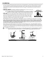
1 . Rotate bypass handles to the bypass mode 

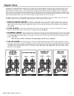
(see Fig. 2 of page 4)

 .


2 . Turn on inlet water and check for leaks in the newly installed plumbing .


3 . Fully open a cold water faucet, preferable at a laundry sink or bathtub without an aerator .


4 .  Wait two to three minutes or until water runs clear, then turn water off and follow start-up instructions .


System regeneration sequence is in the following order . Some sequence differences may be noticed depending upon

local conditions . (If it is desired to change this sequence, please refer to the Dealer Manual or contact the manufacturer .)

    Sequencing for Air Filters:

Air Filters 

(Iron & Sulfur)


1 . Backwash Air 


2 . Backwash 


3 . Regenerant Draw Down (Air draw)  


4 . Return to service


The system is now ready for filling with water and for testing for Air Filters.


NOTE: The “filling” sequence below represents the start-up procedure for Air Filters.

Please reference “Sequence for Various Filters” for proper regeneration sequence (shown above).

1 .   Place the bypass valve into the bypass mode 

(Fig. 2 on page 4)

 .

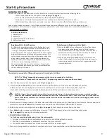
2 .   Press and hold the 

�����

 button until the motor starts . Release button . Put the valve into “BACKWASH” position .

(Please see note above .) Unplug the transformer so that the valve will not cycle to the next position . Open the

inlet handle of the bypass valve very slightly allowing water to fill the tank slowly in order to expel air .

CAUTION:

 If water flows too rapidly, there will be a loss of media to the drain. Certain medias such as carbon, or other dry medias, 

should not be backwashed immediately for extended periods of time. These medias need to “soak” in the water for a 24-hour period 

prior to full backwash conditions. Dry media exposed to water too quickly in backwash will result in media plugging the drain and 

valve assembly. 

3 .  After the water is flowing steadily to the drain, clear and without the presence of air, slowly open the inlet valve . Restore power and 

momentarily press the 

�����

 button to advance the control to the “REGENERANT DRAW DOWN” position .

4 .  With the bypass still in the diagnostic mode 

(Fig. 3 on page 4)

, there should be a slow flow to the drain .

5 .   Press 

�����

 button in sequence until display returns to “TIME .” Place bypass valve in the normal operating mode 

(Fig. 1 on page 4)

 by opening the outlet bypass handle .

6 . 

CONDITIONING OF MEDIA:

  To flush any remaining debris and air from the system again:

  1 . Full open a cold water faucet, preferably at a laundry sink or bathtub without an aerator .

  2 . Wait two to three minutes or until water runs clear, then turn water off .

  3 . Turn on hot water and check for air, then turn water off after air is discharged .
7 . Place unit into regeneration and allow to complete a full cycle . Upon completion, unit will deliver treated water . 

Backwash Air Cycle Feature:

Air filter units are programmed with the backwash air cycle 

feature . This unique feature allows for small movements or 

“inching” of the piston towards the backwash cycle . As the 

piston approaches this cycle, the backwash port opens slightly 

with each advancement, allowing air to escape to drain . This 

cycle is twelve very small mini steps of the piston which take 

place twenty seconds apart . Usually midway between the 

twelve positions, the air begins to be released very slowly to 

the drain in normal operating conditions .

When first starting up an air sulfur or air iron, it is advised to 

step through these positions and go to the normal backwash 

cycle in order to fill the unit . 

To Advance in Backwash Air Cycle:

1 .  Pushing the 

����

 button will advance to each of the twelve 

mini steps within the backwash air cycle . While there are 

usually twelve steps to this cycle, the valve may make two or 

three movements for each step . Wait for these movements 

to complete before pressing 

����

 again .

2 .  Pushing and holding the 

����� 

button for three seconds 

while in the Backwash Air cycle will skip the remaining mini 

steps and proceed to the next cycle of regeneration which 

is usually Backwash .

Start-Up Procedures

Summary of Contents for HFAIR-1054

Page 1: ...lter Iron and Sulfur Air Draw Filters OWNER S MANUAL AND INSTALLATION GUIDE For Models HFFE 1054 HFFE 1354 HFHS 1054 HFHS 1354 HFAIR 1054 HFAIR 1354 100037741 100037742 100037739 100037740 100037743 1...

Page 2: ...rranty 26 Quick Reference Guide 27 YOUR WATER TEST Hardness______________________ gpg Iron___________________________ ppm pH____________________________ number Nitrates_______________________ ppm Mang...

Page 3: ...and days to a regeneration are optional displays For more explanation consult the operating displays and maintenance section Pressing the NEXT button on a general operating screen will cycle through...

Page 4: ...er flows through the control valve for normal operation of a water softener or filter During the regeneration cycle this position provides regeneration water to the unit while also providing untreated...

Page 5: ...subjected to room temperatures under 33 F 4 Do not subject the tank to any vacuum as this may cause an implosion and could result in leaking If there is a possibility a vacuum could occur please make...

Page 6: ...o a subsurface drainage system or other safe location Remember to follow all local codes When installing the drain line on any backwashing filter especially filters that utilize air as the regenerant...

Page 7: ...is necessary to relieve the pressure from the system Place filter into by pass mode Fig 2 Page 4 and release pressure by manually stepping through an entire regeneration sequence This will adequately...

Page 8: ...REGEN UP DOWN NEXT CLOCK REGEN UP DOWN NEXT CLOCK TIME OF DAY MON GPM 2 40 8 PM Press NEXT to cycle to the next step or REGEN to return to the previous step STEP 1 Press and hold the NEXT and UP butt...

Page 9: ...ing steadily to the drain clear and without the presence of air slowly open the inlet valve Restore power and momentarily press the button to advance the control to the REGENERANT DRAW DOWN position 4...

Page 10: ...is installed GPM flashes on the display when water is being treated indicating gallons per minute flowing through the system 2 REGENERATION MODE Typically a system is set to regenerate at a time of no...

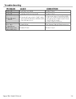
Page 11: ...ERROR appears and flashes alternately with the dealer name and phone number record the ERROR number and contact your servicing dealer promptly This indicates that the control valve was not able to fu...

Page 12: ...TER on PC board C Restricted stalled meter turbine C Remove meter and check for rotation or foreign material D Meter wire not installed securely into three pin connector D Verify meter cable wires are...

Page 13: ...el in regenerant tank G Check refill setting in programming Check refill flow control for restrictions or debris and clean or replace H Damaged seal stack assembly H Replace seal stack assembly I Cont...

Page 14: ...osition or disconnect power supply from PC board for 5 seconds and then reconnect B PC board not properly snapped into drive bracket B Properly snap PC board into drive bracket and then Press NEXT and...

Page 15: ...GEN buttons for 3 seconds to resynchronize software with piston position or disconnect power supply from PC board for 5 seconds and then reconnect Then reprogram valve to proper setting B MAV NHBP mot...

Page 16: ...losed The alarm buzzer will activate and the screen will display the error A Check for low flow leak Press NEXT and REGEN buttons for 3 seconds to resynchronize software with piston position or discon...

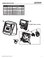
Page 17: ...o Part No Description Qty 1 CV4381 01 Hague Filter Cover 1 2 CV3107 1 Motor 1 3 CV3002A Drive bracket spring clip Includes 5 6 1 4 CV4377WF WF Replacement Board 1 5 CV3110 Drive gear 12 x 36 3 6 CV310...

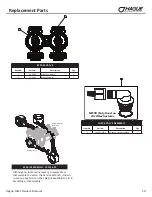
Page 18: ...V3011 1 piston assembly downflow 1 CV3011 01 1 piston assembly upflow 1 CV3407 1 25 piston assembly downflow 1 5 CV3174 Regenerant piston 1 6 CV3001 1 body assembly downflow 1 CV3001UP 1 body assembly...

Page 19: ...1 CHECK VALVE ASSEMBLY Item No Part No Description Qty 1 CH4642 WR A Air check valve assembly 1 Although no tools are necessary to assemble or disassemble the valve the Service Wrench shown in variou...

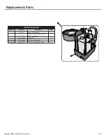
Page 20: ...V3010 1F F injector assembly CV3010 1G G injector assembly CV3010 1H H injector assembly CV3010 1I I injector assembly CV3010 1J J injector assembly CV3010 1K K injector assembly not shown CV3170 O ri...

Page 21: ...08 04 FTG Drain 1 Strt No Sil 1 Water flow Proper DLFC orientation directs water flow towards the washer face with rounded edge DRAIN LINE ASSEMBLY 3 4 Item No Part No Description Qty 1 CH4615 Elbow l...

Page 22: ...Part No Description Qty 1 OZ1 A Ozone Kit Assembly 1 2 OZ1 CASE Enclosure Top Bottom and Clip cover not shown 1 3 33217 WRP3 Ozone Cell 1 not shown CJCPG 6PBLK 3 8 Compression Nut 1 not shown CH4642WR...

Page 23: ...OLVENT Item Part No Description Qty CV3007 07 1 1 4 1 1 2 PVC solvent assembly 2 4 CV3352 Fitting 2 3 4 BRASS SHARK BITE Item Part No Description Qty CV3007 12 3 4 brass shark bite assembly 2 4 CV3628...

Page 24: ...24 Hague Filter Owner s Manual This page intentionally left blank...

Page 25: ...1 0 1 0 pH Range 6 8 to 9 0 6 8 to 9 0 Total Dimensions 10 W x 52 H 13 W x 62 H Weight Filled Lbs 106 5 164 Sulfur Filters Iron Air Filters 1 Op onal Ozone Generator not recommended for use on lters...

Page 26: ...d is owned by the original owner This warranty does not cover expendable or misapplied medias or damages due to accident re ood freezing or any other Act of God We are not responsible for damages due...

Page 27: ...DOWN buttons AM PM toggles at 12 3 Press 4 Adjust minutes with UP and DOWN buttons 5 Press 6 Adjust current day with UP and DOWN buttons 7 Press to complete and return to normal operation CURRENT DAY...

Page 28: ...100037746 RevA0120 Iron and Sulfur Air Draw Filter Hague Quality Water Int l 4343 South Hamilton Road Groveport OH 43125 Phone 614 836 2115 Fax 614 836 5349...

Reviews: