H3C WBC580 G2 Installation Manual Download Page 57


26 

Figure4-44 Uploading a backup file 


To roll back the history configuration, click 

Rollback History

. You can then view and delete 

the rollback history records. 
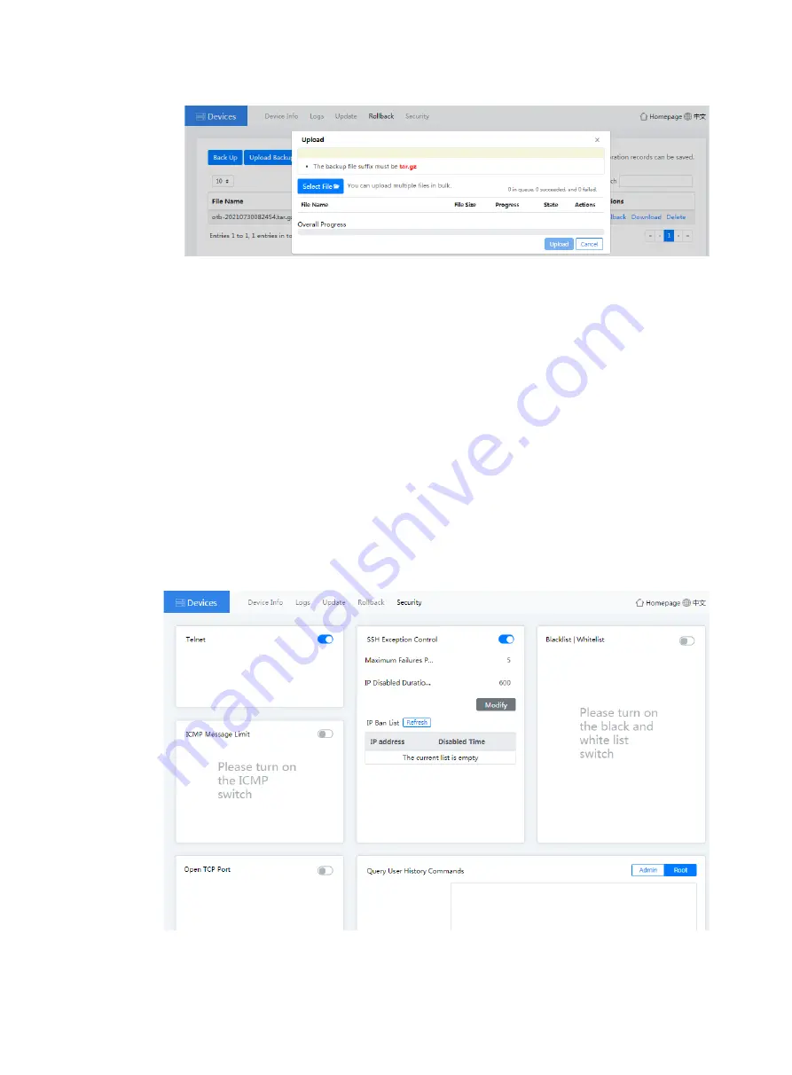
5. 

Click the 

Security

 tab. Then you can configure the following parameters: 


Telnet

—If you disable Telnet, you cannot log in to the device through Telnet to ensure the 

system security. 


SSH Exception Control

—With this feature enabled, the password brute force cracking and 

DOS attacks can be prevented. You can set the maximum failures per minute and IP 
disabled duration. 


ICMP Message Limit

—With this feature enabled, you can prevent the frequent external 

device Ping packets from consuming the system resources. 


Blacklist/Whitelist

—You can configure blacklists and whitelists to control the device 

access. 


Open TCP Port

—With this feature enabled, the external devices can access the device 

only through the configured TCP port. 


Query User History Commands

—You can use this feature to view the user history 

operations to determine whether the issue is caused by user improper operation. 

Figure4-45 Device security page 


Summary of Contents for WBC580 G2

Page 1: ...H3C WBC580 G2 Multiservice Access Controller Installation Guide New H3C Technologies Co Ltd http www h3c com Document version 5W102 20211022...

Page 2: ...espective owners Notice The information in this document is subject to change without notice All contents in this document including statements information and recommendations are believed to be accur...

Page 3: ...e optional x y Braces enclose a set of required syntax choices separated by vertical bars from which you select one x y Square brackets enclose a set of optional syntax choices separated by vertical b...

Page 4: ...s a Layer 2 or Layer 3 switch or a router that supports Layer 2 forwarding and other Layer 2 features Represents an access controller a unified wired WLAN module or the access controller engine on a u...

Page 5: ...Documentation feedback You can e mail your comments about product documentation to info h3c com We appreciate your comments...

Page 6: ...ling a power supply 8 Connecting external cables 8 Cabling guidelines 8 Connecting a mouse keyboard and monitor 9 Connecting an Ethernet cable 9 Connecting a fiber port 10 Connecting a USB device 11 C...

Page 7: ...perations 1 Monitoring the temperature and humidity in the equipment room 1 Examining cable connections 1 6 Appendix A Chassis views and technical specifications 1 Chassis views 1 Technical specificat...

Page 8: ...t burn hazards WARNING To avoid being burnt allow hot surfaces or components to cool before touching them The device or component is heavy and requires more than one people to carry or move WARNING To...

Page 9: ...ve the chest use one more people to help adjust the device orientation Make sure the rack is securely seated on the floor before installing or removing the device To ensure good ventilation install bl...

Page 10: ...pen optical fiber connectors to protect them from contamination and ESD damage Insert dust plugs into open fiber ports and transceiver module ports to protect them from contamination and ESD damage Ex...

Page 11: ...on 75 m 0 2 mg m 3 Dust sedimentation 75 m to 150 m 1 5 mg m 2 h Sand 150 m 30 mg m 3 The equipment room must also meet limits on salts acids and sulfides to eliminate corrosion and premature aging of...

Page 12: ...and rear rack posts Rack requirements Using mounting brackets and an SL 2U FR S short rail kit Height 87 mm 3 43 in 2 RU Width 440 mm 17 32 in Total depth 450 mm 17 72 in 350 to 450 mm 13 78 to 17 72...

Page 13: ...rounded Use foldable antistatic mat and portable repair kit EMI All electromagnetic interference EMI sources from outside or inside of the device and application system adversely affect the device in...

Page 14: ...with the device Prepare them yourself as required Figure1 3 Installation tools Pre installation checklist Table1 7 Pre installation checklist Item Requirements Result Installation site Ventilation A m...

Page 15: ...ectromagnetic shielding for example shielded interface cables is used as required Lightning protection The AC power source is reliably grounded Optional Network port lightning protectors are available...

Page 16: ...ssis cover intact and if you want to open the chassis contact H3C for permission Otherwise H3C shall not be liable for any consequence About the SL 2U FR S short rail kit The SL 2U FR S short rail kit...

Page 17: ...ng bracket installation hole 4 Identification marks 5 Rear mounting clip 6 Rear mounting screw holes Figure2 4 Right outer rail 1 Front mounting screw holes 2 Front mounting clip 3 Mounting bracket in...

Page 18: ...rity screws a As shown by callout 1 in Figure2 6 align the four keyhole slots in the inner rail with the pegs on the chassis side panel and place the inner rail against the side panel b As shown by ca...

Page 19: ...rack post The front ends of the outer rails provide threaded screw holes You are not required to install M6 cage nuts in these screw holes Figure2 8 Installing cage nuts 4 Attach an outer rail to the...

Page 20: ...of the outer rail to the rear rack post As shown by callout 1 in Figure2 10 align the screw holes in the rear end of the outer rail with the cage nuts in the rear rack post and insert the mounting cli...

Page 21: ...talled at the same height so that the device can be installed safe and level on the rack Figure2 11 Left and right outer rails installed Installing the device in the rack 1 Slide the inner rails on th...

Page 22: ...g brackets of the device flush against the front rack posts Then use captive screws to secure the mounting brackets to the front rack posts As a best practice use a torque of 30 kgf cm 2 94 Nm to fast...

Page 23: ...al cables Cabling guidelines WARNING To avoid electric shock fire or damage to the equipment do not connect communication equipment to RJ 45 Ethernet ports on the device For heat dissipation make sure...

Page 24: ...nectors on the device For a PS2 mouse and keyboard insert the USB connector of the USB to PS2 adapter to a USB connector on the device Then insert the PS2 connectors of the mouse and keyboard into the...

Page 25: ...ansceiver module are connected to the Rx and Tx ports on the peer end respectively No transceiver modules are provided with the device Purchase transceiver modules yourself as required For transceiver...

Page 26: ...re hot swappable To connect a USB device 1 Connect the USB device to the USB connector as shown in Figure2 20 Figure2 20 Connecting a USB device to a USB connector 2 Verify that the device can identif...

Page 27: ...into the receptacle on the power supply 4 Slide the cable clamp forward until it is flush against the edge of the power cord connector 5 Connect the other end of the power cord to the power supply sy...

Page 28: ...vice For more information see Powering off the device 2 Remove the device from the rack For more information see Removing the device from a rack 3 Remove the power cord from the power supply a Open th...

Page 29: ...14 Figure2 24 Removing the power supply...

Page 30: ...mation about how to log in to HDM see Logging in to HDM from the Web interface 2 From the navigation pane select Power Manager Power Control The power control configuration page opens 3 Select Power o...

Page 31: ...navigation pane select Power Manager Power Control The power control configuration page opens 3 Select Force power off or Graceful power off and then click Execute to put the device in standby mode 4...

Page 32: ...time monitoring on device health state and CPU usage Restrictions and guidelines As a best practice use one of the following browsers to access the Web interface Chrome 48 or higher Internet Explorer...

Page 33: ...ollowing tasks Connect the HDM shared or dedicated port on the server to the network The HDM shared network port transmits HDM management traffic and server data traffic simultaneously The HDM dedicat...

Page 34: ...rst login enter the default username admin and password Password _ Figure4 2 HDM login page Logging in to the remote console You can manage the device and install an operating system OS from a remote...

Page 35: ...rsion of OpenJDK 2 Install the IcedTea Web plugin Open the msi installation file of the target version for the plugin and install the plugin with the default settings 3 Run HDM KVM a Access the instal...

Page 36: ...e In this example the package name is icedtea web x86_64 Figure4 5 Installing the IcedTea Web plugin 2 Install the OpenJDK Java environment a Use either of the following methods to install OpenJDK If...

Page 37: ...ermission from the primary user Then the primary user has only the read only permission The primary user can grant full permission to any secondary user when closing the KVM window If the primary user...

Page 38: ...ches an H5 KVM remote console Encrypted modes transmit encrypted data and provide better security performance Unencrypted modes transmit unencrypted data and provide higher transmission speed The remo...

Page 39: ...s as shown in Figure4 11 Figure4 11 Authorizing remote console access Parameters Dedicated mode Includes Encrypted dedicated mode and Unencrypted dedicated mode A dedicated mode allows for only one re...

Page 40: ...only view videos and screenshots and record videos You cannot perform any configuration tasks If your access is denied the KVM window closes If the primary user does not respond in 30 seconds you are...

Page 41: ...10 Figure4 13 Oasis platform Web interface Figure4 14 AC Web interface...

Page 42: ...terface 4 Click Manage at the right corner of the Oasis Platform ACs or License Server icon to access the O M page The Oasis platform O M page AC O M page and license server O M page are as shown in F...

Page 43: ...12 Figure4 16 Oasis platform O M page Figure4 17 AC O M page...

Page 44: ...to log in to the device In the Internet Explorer browser enter the complete URL of the WBC Monitoring Platform in the format of https IP Port zh cn login To log in to the device from the WBC Monitorin...

Page 45: ...ACs and License server to access the Oasis platform AC and license server Web interface respectively The Oasis platform Web interface AC Web interface and license server Web interface are as shown in...

Page 46: ...ter the default username oasis_root and password oasis_root123456 Figure4 21 Oasis platform login page Logging in to the AC IMPORTANT By default AC is enabled To disable AC see Managing the AC The fac...

Page 47: ...this is the first login enter the default username admin and password admin Figure4 22 AC Web interface login page Logging in to the license server 1 Connect the PC to the device 2 Launch the browser...

Page 48: ...ge The Oasis platform O M page is as shown in Figure4 24 Figure4 24 Oasis platform O M homepage 2 Click the Logs tab you can view the detailed logs and perform the following tasks To delete a log file...

Page 49: ...nfigure two devices to back up each other to ensure service continuity In the Configure HA area you can configure the following parameters HA ID The HA ID must be unique in the Layer 2 network The HA...

Page 50: ...backup interval c To configure an immediate HA task select Synchronize Thus the local device will back up the data to the remote device immediately 5 Click the Monitor tab to view the component status...

Page 51: ...log folder name and select Delete To download logs you can right click a log folder name and select Download or click Download in the right corner of the page Figure4 31 AC logs page 3 Click the Updat...

Page 52: ...ded to the AC close the dialog box Figure4 33 Uploading a file b Click Update in the Actions column In the dialog box that opens click OK Figure4 34 Updating the AC version Managing the license server...

Page 53: ...d or click Download in the right corner of the page Figure4 36 License server logs page Managing the device On the Devices page you can view device information print logs update device version back up...

Page 54: ...lth score CPU usage memory usage disk usage and network I O rate CPU View related CPU information Memory View related memory information Disk View related disk information Figure4 37 Devices homepage...

Page 55: ...tures normally Figure4 39 Device update page a Optional Click Upload In the dialog box that opens click Select File select a file for upload and then click Upload After the file is uploaded to the Oas...

Page 56: ...the system will update the current system version to the specified system version 4 Click the Rollback tab to back up the configuration or rollback the history configuration Figure4 41 Device rollbac...

Page 57: ...cks can be prevented You can set the maximum failures per minute and IP disabled duration ICMP Message Limit With this feature enabled you can prevent the frequent external device Ping packets from co...

Page 58: ...d correctly Keep the network topology up to date to facilitate troubleshooting of networking problems Maintenance tools The following tools are required for device maintenance Temperature humidity met...

Page 59: ...ecklist The cable type is correct The cables are correctly and firmly connected and the cable length is appropriate The cables are in good condition and are not twisted or corroded at the connection p...

Page 60: ...RJ 45 Used together with an Ethernet cable to provide network connection USB connector USB 2 0 Used for connecting the following USB devices USB flash disk USB keyboard or mouse USB optical drive SFP...

Page 61: ...4TB 6G SATA 7 2K 3 5in HDD General Intelligent Disk Equipment Module FIO Power supply 550W power supply Power consumption 194 1 W Rated input voltage 100 to 240 VAC 50 or 60 Hz Network ports 2 embedd...

Page 62: ...Replace the drive immediately Steady blue Steady green Flashing green The drive is operating correctly and is selected by the RAID controller Off Flashing green The drive is performing a RAID migrati...

Page 63: ...m HDM Fast flashing HDM is restarting To restart HDM press the UID button LED for eight seconds Off UID LED is not activated Health LED Steady green The system is operating correctly or a minor alarm...

Page 64: ...g correctly Fast flashing green Power is being input correctly but the system is not powered on Slow flashing green The power supply is for backup and provides no power output Steady amber Either of t...

Page 65: ...iber views The device provides SFP ports To connect an SFP port on the device use an SFP transceiver module and an optical fiber with LC connectors Figure8 1 SFP transceiver module Figure8 2 SFP trans...

Page 66: ...MM850 A specifications Item Specification Central wavelength 850 nm Max transmission distance 550 m 1804 46 ft Transmission rate 1250 Mbps Connector type Duplex LC Fiber mode MMF Fiber diameter 50 m...

Page 67: ...cification Central wavelength 850 nm Max transmission distance 300 m 984 25 ft Transmission rate 10 3125 Gbps Connector type Duplex LC Fiber mode MMF Fiber diameter 50 m 62 5 m Transmit power 7 3 to 1...

Reviews: