


EN
41
Operating manual
ARCPULL 700
Translation of the original
instructions
Ignition:
the consumable (pulling ring or threaded studs, etc.) is brought into contact with the support sheet. Pressing
the trigger will start the welding process: the power source sends a current to the threaded stud, the gun raises the
threaded stud slightly and a low-intensity electric arc is created.
Cleaning:
this phase could also be called preheating. The power source regulates a current to ensure a low intensity
electric arc, the heat generated by this arc allows:
- to burn off impurities from the support sheet (grease, oil and electrolytic zinc coating)
- to pre-heat the two parts and limit the welding arc’s thermal shock in order to improve the weld’s quality
During this phase, neither the consumable nor the support sheet is melted. Also, this phase does not remove the zinc
coating from the galvanised sheet.
Drawing the arc:
the power source significantly increases the current to create a high-energy arc that creates a weld
pool on the support sheet and melts the end of the consumable.
Fastening:
The gun plunges the consumable into the weld pool.
5. THREADED STUD DESIGN AND WELD POOL PROTECTION
The types of consumables (different shapes, sizes and materials) designed for drawn-arc welding are listed in stan
-
dard ISO 13918. In addition to low-carbon steel, stainless steel and copper-plated steel inserts, this product can also
weld certain aluminium consumables.
5.1. THE SUPPORT SHEET’S SURFACE FINISH AND CLEANING PROCESS
The support part must be completely grease free when welding consumables. It is also necessary
to clean this support part if it has been chemically treated (with a zinc coating for galvanised steel,
anti-corrosive coating for heat-treated steel or alumina for aluminium).
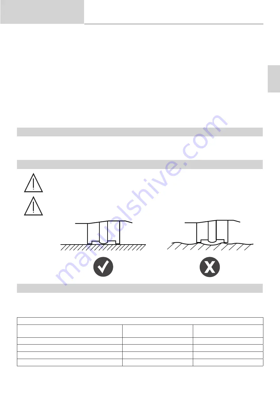
Welding consumables, especially aluminium ones, must be done on a flat support part.
5.2. THICKNESS OF THE SUPPORT SHEET DEPENDING ON THE THREADED STUD’S DIAMETER
With the exception of specific car-bodywork applications (pulling ring and earthing chuck placement), the support
sheet’s thickness should not be less than ¼ of the diameter of the consumable’s base when working with steel, and ½
of the diameter when working with aluminium.
Some examples (non-exhaustive list)
Parts to be welded
(according to ISO 13918)
Base diameter
Minimum sheet thickness
Steel threaded stud (type DD M12)
12 mm
3 mm
Steel threaded stud (type PD M6)
5.35 mm
1.3 mm
Stud support (SD ⌀ 10)
10 mm
2.5 mm
AlMg short-time stud (type PS M8)
9 mm
2 mm