GVS K-BUS AMRW-24/10.1 User Manual Download Page 41

K-BUS

R

KNX/EIB

Switch Blind Actuator

41

www.video-star.com.cn

[email protected]

Tel.

:(

8620

39338986

Fax

:(

8620

39338465

5. Communication Objects Description

Communication object is the media of devices on the bus communicate with other device, that is, just

communication object can communicate with the bus. The role of each communication objects as following.

Note: “C” in “Flag” column in the below table means that the object has a normal link to the bus; “W”

means the object value can be modified via the bus; “R” means the value of the object can be read via the bus; “T”
means that a telegram is transmitted when the object value has been modified; “U” means that value response
telegrams are interpreted as a write command, the value of the object is updated.

5.1

Communication objects of Switch outputs

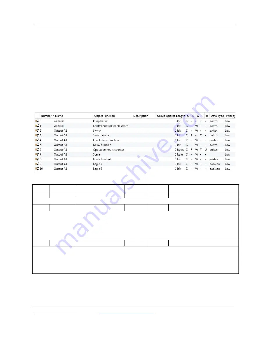
5.1 Communication objects of switch outputs

No.

Function

Object name

Data type

Flags

DPT

0

General

In operation

1bit

C,T

1.001 DPT_Switch

This object is always visible, used to send telegram “1” to the bus periodically to proof the device is under normal working condition.
1

General

Central control for all switch

1bit

C,W

1.001 DPT_Switch

This object is used for the central control for all switch outputs if the central control of output is enabled.

Telegram value

0 ——off

1 —— on

2

Output X

Switch

1bit

C,W

1.001 DPT_Switch

This object is used to trigger the switch operation. It will start the switch operation with “1”, and end with “0”. When enabling

“input 0” in the logic function, the object “Switch, X” will be subject to logic functions, rather than trigger the switch operation directly.

For details, please refer to the following flowchart:

Summary of Contents for K-BUS AMRW-24/10.1

Page 1: ...r Electronics Industrial Co Ltd www video star com cn marketing video star com cn Tel 8620 39338986 Fax 8620 39338465 K BUS R Switch Blind Actuator User Manual Ver 1 2 AMRW 24 10 1 KNX EIB Intelligent Installation Systems ...

Page 2: ...620 39338465 User manual update instructions Ver Date Edit contents Edit position 1 0 2017 1 4 Published the first edition 1 1 2017 4 11 1 Add function of the parameter When blind is under end position up down object function is Chapter 4 4 1 page 29 1 2 2017 5 25 Add connection diagram of blind Chapter 3 2 page 8 ...

Page 3: ...1 2 Time 17 4 3 2 1 Selection Delay 18 4 3 2 2 Selection Flashing 19 4 3 2 3 Selection Staircase 20 4 3 3 Parameter window X1 2 Logic 21 4 3 4 Parameter window X1 2 Scene 24 4 3 5 Parameter window X1 2 Forced 25 4 3 6 Parameter window X1 2 Operation hours counter 26 4 4 Shutter outputs A L 27 4 4 1 Parameter window Channel X Shutter 27 4 4 1 1 Parameter window X Drive 31 4 4 1 2 Parameter window X...

Page 4: ...the Switch Blind actuator for users as well as assembly and programming details and explains how to use the Switch Blind actuator by the application examples The function of the Switch Blind actuator is summarized as follows Switch output which can connect some electrical loads such as lighting sockets There are 24 outputs the power of the load is 230V AC 10A output with manual button controlling ...

Page 5: ...tion 0 100 only Shutter working mode Set 8 scenes store or recall via a 1byte object Automatic sun protection Safety function Status response query and reply the current shutter blind position and operation mode to the bus thereby indicating the status in the visualization device Two working mode Blind and Shutter Programmers are able to use the Engineering Tool Software ETS ETS4 version or above ...

Page 6: ...105uF Max switching current 16A 240V AC Mechanical endurance 2 x 10⁶ Electrical endurance 5 x10⁴ Max DC current switching capacity resistive load 16A 30V DC Connection EIB KNX Via bus connection terminals red black Ø0 8 mm Outputs A B C1 Screw terminals Wire Range0 5 4mm2 Torque 0 8N m Other outputs Screw terminals Wire Range 0 5 2 5mm2 Torque0 5N m Operation display Programming button red LED For...

Page 7: ...of several lamps in parallel the load will be reduced although the power is unchanged but the instantaneous impact of current will increase and easy to make the relay contacts melted So in normal use subject to the measured current the measured maximum inrush current must be within the allowable range Application program Model Max number of communication objects Max number of group addresses Max n...

Page 8: ...K BUS R KNX EIB Switch Blind Actuator 8 www video star com cn marketing video star com cn Tel 8620 39338986 Fax 8620 39338465 3 2 Connection diagram ...

Page 9: ...to control A B C D When the indicator LED is GREEN G the output of operation buttons can be used to control E F G H When the indicator LED is R G the output of operation buttons can be used to control I J K L The output of operation button When control switch output via the button the indicator LED near the button indicates the output state the LED on is output off is no output When control curtai...

Page 10: ...operation delay finished the operation during this process will be recorded and executed after the delay over Meanwhile telegrams sent during the scan delay will be recorded and executed after the delay The delay time here does not include the initiation time of the device normally it will take 3 seconds to re initiate the device after power voltage recovery I e the delay will start counter after ...

Page 11: ... limit time of sending telegrams Options 100ms 500ms 10min After bus voltage recovery when the initialization time and the scan and relay operation delay have been completed the set period begins and counting the telegrams also begins Once the max number of telegrams has reached during the set period the device will not send telegram to the bus until the next set period start and the telegrams tha...

Page 12: ...ng press the Man Button or the set time for the manual to automatic has elapsed Parameter Delay time 1s 10 60000 The parameter appears when both long press and automatic delay time is selected in the parameter manual to automatic by It is used for setting the time for an automatic reset from the manual operation to automatic operation state after the last push button operation Options 10 60000s No...

Page 13: ...utputs A L There are max 24 outputs Each output can be set separately and parameters and objects which are assigned to each output are the same Using output A1 as an example described 4 3 1 Parameter window Channel X1 2 Parameter window Channel X1 2 can be shown in fig 4 3 which applies to a whole output In addition to setting general switching function but also set position of switch on the bus p...

Page 14: ...atus on bus voltage recovery via this parameter Options unchange Open Closed As before as bus fail When selecting Unchanged the contact of the relay will remain the same as the last status on the power on When selecting open the contact will be open while it is closed when selecting closed The contact position after voltage recovery is the same as that before power off with As before bus voltage f...

Page 15: ...e bus There are three options to select Options Respond after read only respond after change respond always If selecting respond after read only the status telegram will not be sent out until receiving a read request telegrams via the object reply switch status from the bus If selecting respond after change it will send the status immediately via the object reply switch status when there are any c...

Page 16: ...g value and defines the direction of the contact after receiving it The details can be found in the below form Parameter options Switch X object value 1 Switch X object value 0 Open Contact open OFF Contact close ON close Contact close ON Contact open OFF Since the switch and logic functions share the same object switch X thus need to understand the relationship between them the control sequence s...

Page 17: ...set the special functions individually in Fig 4 5 Enable or disable the special function in X1 2 Function Options Disable Enable Fig 4 5 the special function enable window X1 2 Function 4 3 2 Parameter window X1 2 Time This parameter window will become visible when selecting enable in the parameter Function of time in the window X Function shown in Fig 4 5 See Fig 4 6 And the object enable time fu...

Page 18: ...ch in Fig 4 6 will be shown when selecting Delay The delay switch can be started via the object Delay function Parameter Delay for switch on 0 240 min 0 59 s This parameter defines the delay time of switching on Options 0 240 min 0 59s After receiving the delay ON telegram the switch is on once the delay over Parameter Delay for switch off 0 240 min 0 59 s This parameter defines the delay time of ...

Page 19: ...tch on 0 240Min 0 59s The parameter defines the duration time of switch on the output when flashing Options 0 240 min 0 59 s Note it will not be executed unless the time is lower than the relay threshold switch frequency Since there will be not sufficient energy to do it because of the frequent relay switching and it may cause the time delay The same situation will happen after the bus voltage rec...

Page 20: ... when selecting star with 1 stop with 0 it will stop flashing with 0 The stop position is defined via last parameter It will start flashing with value 0 when selecting star with 0 stop with 1 it will stop flashing with 1 The stop position is defined via last parameter It will start flashing with either 1 or 0 when selecting star with 1 0 can not be stopped Under this circumstance it cannot termina...

Page 21: ...ng Start with 1 no action with 0 it will switch on the staircase lights with the value 1 and no reaction with 0 When selecting Start with 0 1 cannot be stopped it will switch on the staircase lights either with 0 or 1 but cannot stop it until the duration time finished or changed by other operation When selecting Start with 1 off with 0 it will switch on the staircase lights with the value 1 and o...

Page 22: ...the value of Input 2 of logic This operation will ignore the objects which are unable and continue to the next step with the ones who are enabled Parameter Enable input 0 This parameter is used to enable the function of logic operation of input 0 whose values are wrote by the object Switch Options Disable Enable In the both cases of input 0 enabled and not enabled there are a little different para...

Page 23: ...ans the value of input 0 can be used as the operation result if the value of input 2 is 1 that means the operation value of input 0 1 can be used as the result Options AND OR XOR Gate function Below result of logic operation is possible Logic function Object values Description Input0 Switch Input1 Result of Input0 1 Input2 Output AND 0 0 1 1 0 1 0 1 0 0 0 1 0 1 0 1 0 0 0 1 The result is 1 if both ...

Page 24: ...d and the output is directly determined by the input2 Parameter Result reverse This parameter defines whether negate the logical operation results Negate it with yes don t with no Options No Yes Parameter Value of input 1 after bus recovery This parameter defines the default value of the object Logic1 after bus voltage recovery Options 0 1 Value before power off Parameter Value of input 2 after bu...

Page 25: ...n be set per output Options Scene 1 Scene 64 0 no assignment Note 1 64 in the parameter setup corresponds to the scene number 0 63 received by the communication object Scene If a scene is modified the new scene will be stored when power off Parameter Standard output value is This parameter defines the switch output status when recall the scene Options Open Close 4 3 5 Parameter window X1 2 Forced ...

Page 26: ...other operation can be performed 10b 2 Force switch off 11b 3 Force switch on When cancel the forced operation the position of relay contact is unchanged Parameter Contact position if forced operation The parameter is visible if the option 1bit is selected via last parameter which defines the contact position of force operation Option Unchange Open Close The forced operation has the highest priori...

Page 27: ...lue in h 0 100 0 not send only for reading The parameter determines the time interval to send the telegram which is used for counting the time of relay on Option 0 100 0 means do not send 1 100 means 1 hours to 100 hours cyclically send the value 4 4 Shutter outputs A L There are max 12 outputs Each output can be set separately and parameters and objects which are assigned to each output are the s...

Page 28: ...rate the curtain with louvres If selecting Blind the output is similar with the Shutter operation mode except that it cannot adjust louvres The section details the parameters and communication objects for the Shutter mode Parameter Motor type This parameter is used to set the mode of shutter drive Options AC motor Dry contact motor The option AC motor is applied to driver of AC power The option Dr...

Page 29: ...e the current position and then into the target position Only the Shutter finish a full running can confirm position Parameter If bus failure position is The parameter is used to set the position where shutter moves after on bus voltage failure Options Unchang Up Down Stop If the option Unchange is set the output contacts remain in their current position If the option up is set the Shutter is move...

Page 30: ...or right to the bottom Depending on the parameter settings the Shutter either remains in the reference position after the reference movement or moves back into the saved position Parameter position of slat after arriving on lower end position The parameter can set the slat positions of slat after the lower end position is reached Options 0 10 90 100 For example if select 40 when the object Shutter...

Page 31: ...nt to know its technical data and running time before using the Shutter It is the only way that the relevant parameters can be set precisely for the Shutter actuator Fig 4 14 parameter window X Drive Parameter Total move time 20 50000 0 1s The parameter is used for setting the total move time in seconds The total move time is the period that the Shutter requires to travel from the upper limit posi...

Page 32: ...e to calculate the current position of the Shutter precisely Parameter duration of slat adjustments 10 250 10ms The parameter is used for setting the duration of slat adjustment in milliseconds The shorter the time the more precise angle adjustment of slats After an upward movement of the Shutter the slat normally are open horizontal slat position If the Shutter is now lowered the slat are closed ...

Page 33: ...ction and extend the service life of the motor Parameter Additional travel time in upward direction 0 255 0 1s The parameter set a additional travel time in upward direction When the Shutter reach the completely up position the output is disconnected after a delay time If the position does not reach completely up the output will be disconnected without delay Other case is after reached the complet...

Page 34: ... receives a telegram 1 the Auto Operation is activated When the object Enable auto control receives a telegram 0 or the user sends a direct movement command e g UP DOWN move to position etc the Auto Operation is deactivated If the command is not belong to the direct movement command e g store scene etc the Auto Operation is still activated The priority of direct operation and automatic operation i...

Page 35: ...n is defined I e after the automatic operation has been deactivated for the direct operation or the object Enable auto control it can be automatically reactivated when the set time has elapsed If the automatic operation is interrupted during the set time by a direct operation or object Enable auto control the time will re timing Note the safety operations have the higher priority It is therefore t...

Page 36: ...ainly to prevent component damage or affect the motor life due to light frequent fluctuations lead to the Shutter actuator frequent action Option 0 65535 s Parameter Position if sun 0 Sun is not shining This parameter is similar with last parameter The difference is that here defined the position that the shutter is moved into when the object Sun operation receives a telegram 0 Parameter Delay tim...

Page 37: ...r as to whether there is direct sunlight on the window Once the delay period has elapsed the Shutter actuator positions the shutter blind according to the set Position for sun 1 sun or Position for sun 0 no sun 4 4 1 3 Parameter window X Scene The Parameter window X Scene is shown in fig 4 16 Here can set 8 scenes for per output Fig 4 16 Parameter window X Scene Parameter Overwrite scene stored va...

Page 38: ...0 0 top 100 bottom Parameter slat position 0 100 0 opened 100 closed This parameter is used to set the preset position of slat for a scene 0 100 0 opened 100 closed 4 4 1 4 Parameter window X Safety The Parameter window X Safety is shown in fig 4 17 Here can set safety operation of shutter actuator Fig 4 17 Parameter window X Safety Here define the action that the shutter should be carried out whe...

Page 39: ...tion after triggering Safety operation x x 1 2 Options Unchanged Up Down Stop Parameter cyclic monitoring time in s 0 65535 0 no monitoring The parameter defines the monitoring time at which the safety operation is monitored The monitoring time in the Shutter actuator should be at least twice as long as the cyclical sending time of the sensor so that the Shutter is not immediately moved to the pro...

Page 40: ...peration 2 is higher than that of 1 4 4 2 Parameter window Channel X Blind The Blind operation mode is similar with the Shutter operation mode in the parameters and the objects and their function is also almost the same The only difference is that there is no slat adjustment function in the Blind operating mode Shutter and Blind difference as shown The functions described for the Shutter operating...

Page 41: ...ommand the value of the object is updated 5 1 Communication objects of Switch outputs 5 1 Communication objects of switch outputs No Function Object name Data type Flags DPT 0 General In operation 1bit C T 1 001 DPT_Switch This object is always visible used to send telegram 1 to the bus periodically to proof the device is under normal working condition 1 General Central control for all switch 1bit...

Page 42: ...espond always The object will not send current status to the bus until the device received the request of reading the switch status from the other bus device operation or the bus 4 Output X Enable time function 1bit C W 1 003 DPT_Enable This object will be enabled only when enabling the time function it can be used to enable and disable the time function It will enable the timing function when rec...

Page 43: ...byte C W 18 001 DPT_SceneControl It is able to recall or save the scene when sending an 8 bit command by this object which will be enabled when enabling the scene function The definition of the 8 bit command will be described below Assuming an 8 bit command binary coding as FXNNNNNN F recall the scene with 0 save the scene with 1 X 0 NNNNNN scene number 0 63 1 64 in the parameter setup corresponds...

Page 44: ...ed when selecting enable in the parameter The input 2 of logic which is used to modify logic value of input 2 Table 5 1 Communication objects table Switch output 5 2 Communication objects of Shutter outputs Fig 5 2 Communication objects of shutter outputs NO Function Object name Data type Flags DPT 0 General In operation 1bit C T 1 001 DPT_Switch As above 1 General Central control for all switch 1...

Page 45: ...ter Blind is fully raised then move to the target position 1 first the Shutter Blind is fully lowered then move to the target position The detail process is described in relevant parameter chapter 5 Output X Shutter Blinds position 0 100 1byte C W 5 001 DPT_Scaling If this communication object receives a telegram value the Shutter Blind moves to the corresponding position for the received value In...

Page 46: ...en reaching the target position Telegram value 0 top intermediate position 100 bottom 9 Output X Slat position status 1byte C R T 5 001 DPT_Scaling The object is used for sending the position of the slat to bus when reaching the target position It is only visible in shutter mode Telegram value 0 slat opened to maximum intermediate position 100 slat closed to maximum 10 Output X Sun operation 1bit ...

Page 47: ... C W 1 005 DPT_Alarm The communication object is used to receive a special 1bit telegram from some sensors sending cyclically Such as the cancel safety operation of telegram is 1 if the object doesn t receive the telegram 1 from the sensor during the monitor period the actuator will think that the sensor malfunctions and then triggered the safety operation and make the shutter move to a safety pos...

Reviews: