background image

Mobile NVR M1142 Quick Start Guide

7

Take a Tour

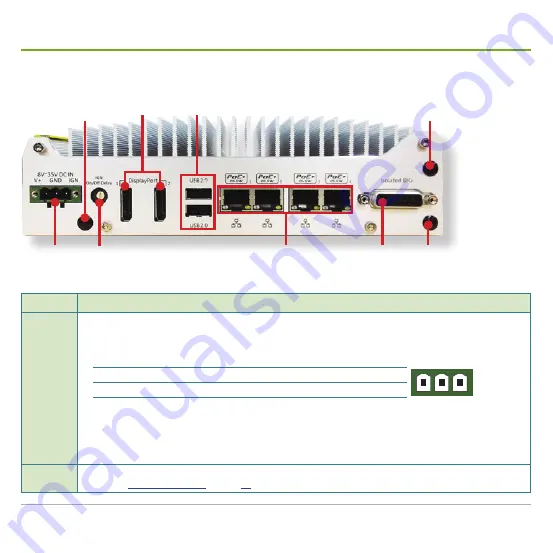
Rear I/O Ports

DC-in 

power 

jack

Power 

on/off delay 

switch

PoE 

ports

4-in / 4-out 

isolated DIO 

connector

Antenna 

aperture 

1

USB 2.0 

ports

DisplayPorts

Antenna 

aperture 

2

Antenna aperture 3

Title

Description

DC-in power 

jack

3-pin DC-in power jack with ignition support.


A  wide range of power input from +8 to +35 V 

including the prevalent 12V and 24V vehicle power system

.


Pin definition:

Pin

Description

In-vehicle deployment example

V+ GND IGN

V+

Positive polarity of DC-in power Connected to car battery (12V/24V)

GND

Ground of DC-in power

Connected to battery GND

IGN

Ignition signal input

Connected to the ACC power of vehicle

Cautions:

1.  Be sure about the DC-in power voltage you are going to tap. Supplying power over 35V will damage the system.

2.  The ignition input allows ACC power of car (12Vdc) or bus/truck (24Vdc). Supplying power over 35V to the ignition 

input will damage the system.

Antenna 

aperture 1

An antenna aperture for WiFi antenna.


See also 

Install a WiFi Module

 on page 

19

 for more details.

Summary of Contents for M1142

Page 1: ...GVD Mobile NVR M1142 Quick Start Guide...

Page 2: ......

Page 3: ...16 Remove Bottom Cover 17 Install a WiFi Module 19 Install a SIM Card 23 Install a 3G or 4G plus GPS Module Optional 24 Mount the Mobile NVR 28 Wire DC in Power Source 30 Manage Ignition Power 32 Wire...

Page 4: ...energy and if not installed and used in accordance with the instruction manual may cause harmful interference to radio communications Operation of this equipment in a residential area is likely to ca...

Page 5: ...the GVD certified hard disk drives at the link below http www gvdigital com gvdweb html document Support_Lists Certified 20HDD 20List pdf NOTE GVD does not guarantee the system performance if a HDD m...

Page 6: ...Mobile NVR M1142 Quick Start Guide iv...

Page 7: ...to go inside the mobile NVR the control center can instantly locate the vehicle that carries the mobile NVR on the map Also on option is a G sensor to measure the vibration every couple of minutes and...

Page 8: ...a RP SMA male body female inner contact A few screws to fix the module Stainless steel round philips screws Wall mount Kit 1 wall mount bracket 8 x rubber bumpers 8 x M4 screws Thermal Pad One piece o...

Page 9: ...l Antenna Length 300cm RP SMA male body male inner contact A few screws to fix the module Stainless steel round philips screws North America Latin America Sierra Wireless AirPrime MC7354 w 15cm intern...

Page 10: ...There must be no less than 5 seconds between each power on off The PWR status LED lights green when the system is powered on Reset button Restarts the system without turning off the power To prevent...

Page 11: ...tatus LED is associated with the half size PCIe Mini Card socket on the motherboard See also Half size PCIe Mini Card socket on page 11 Mic in Line out Speaker out green and microphone input pink Impl...

Page 12: ...r OS installation or co working with the internal HDD SSD for RAID 0 or 1 See also Hot swap a SATA HDD SSD on page 16 USB 3 0 port Four USB 3 0 ports that run with xHCI eXtensible Host Control Interfa...

Page 13: ...finition Pin Description In vehicle deployment example V GND IGN V Positive polarity of DC in power Connected to car battery 12V 24V GND Ground of DC in power Connected to battery GND IGN Ignition sig...

Page 14: ...n off delay When the mobile NVR is set to this mode only the power button on the front panel is available to power on off the mobile NVR Mode 1 is the AT mode which is the default setting In this mode...

Page 15: ...t from the left is implemented with Intel 82579LM controller while the others are implemented with Intel I210 And the PoE port 1 supports Wake on LAN and Intel AMT to support some advanced features su...

Page 16: ...Onboard I O Ports SIM card socket 2 SATA power connector 1 Half size PCIe Mini Card socket SATA data connector 1 SATA data connector 2 SATA power connector 2 Full size PCIe Mini Card socket SIM card s...

Page 17: ...4 Half size PCIe Mini Card socket This socket is provided with x1 PCI Express and supports USB signals It can be loaded with a WiFi module of half size PCIe Mini Card form factor A dedicated status LE...

Page 18: ...green when data transmission is active The socket is associated with this status LED the one that is in the center among the three See also Front I O Ports on page 4 SATA data connector 2 A 7 pin SAT...

Page 19: ...pet door Follow the guide below to open the pet door 1 Place the mobile NVR upside down on a flat surface Then loosen and remove the screw that fixes the pet door at the bottom cover Here is a cutout...

Page 20: ...DD SSD see Hot swap a SATA HDD SSD on page 16 1 Open the pet door as described in Open Pet Door on page 13 The inside motherboard of the mobile NVR then comes to view Part the pet door from the mobile...

Page 21: ...d and slightly push it to make it stick to the thermal pad Then fix the HDD SSD to the pet door by fastening 4 screws 5 Pull the SATA connector from the motherboard Pull the SATA connector from the mo...

Page 22: ...t The door has a lock 2 From the accessories have one of the keys to the door lock Stick the key and turn it to the unlock position as printed on the door 3 Pull at the door handle Pull at the door ha...

Page 23: ...age 13 The pet door is removed 2 From the top cover of the mobile NVR Loosen and remove the 4 screws as illustrated below 3 See the illustration below From the front panel of the mobile NVR remove 5 s...

Page 24: ...mSATA socket for a 3G 4G and GPS module with a SIM card socket Half size PCIe Mini Card socket for a WiFi module Full size PCIe Mini Card socket for a 3G 4G and GPS module with a SIM card socket 5 To...

Page 25: ...Fi module to the mobile NVR 4 Plug the Wi Fi module to the socket s connector by a slanted angle Fully plug the module and note the notch among the module s contact pins should meet the break of the c...

Page 26: ...l antennas as illustrated below WiFi WiFi 3G 4G GPS GPS 3G 4G 7 See the illustration below Pull the other end of the antenna wire which is a SMA connector jack through Antenna aperture 1 on the rear p...

Page 27: ...e outside accessible SATA HDD SSD come within reach re connect the cables to the motherboard Then continue to slide util the bottom cover cannot be slid anymore When the SATA cables for the outside ac...

Page 28: ...te If the mobile NVR has more than one wireless modules installed it is recommanded that you lay out the antenna wires and the external antennas as illustrated below WiFi WiFi 3G 4G GPS GPS 3G 4G 15 P...

Page 29: ...Find the SIM card holder for 3G 4G on the motherboard Full size PCIe Mini Card socket for 3G or 4G plus GPS SIM card holder for 3G and 4G 3 Push back the hinged cover to open the holder 4 Swivel the h...

Page 30: ...he contact pins Full size socket Connector s break Full size PCIe Mini Card socket for a 3G 4G or GPS module with a SIM card holder 4 Plug the module to the socket s connector by a slanted angle Fully...

Page 31: ...won t get stuck Arrange the flat side of the SMA connector to meet the flat side of the antenna aperture Pull the SMA connectors through the antenna apertures exactly as shown GPS SMA connector 3G 4G...

Page 32: ...the outside accessible SATA HDD SSD come in reach re connect the cables to the motherboard Then continue to slide util the bottom cover cannot be slid anymore When the SATA cables for the outside acc...

Page 33: ...antenna Note If the mobile NVR has more than one wireless modules installed it is recommanded that you lay out the antenna wires and the external antennas as illustrated below WiFi WiFi 3G 4G GPS GPS...

Page 34: ...t from the accessories of the mobile NVR The kit includes eight rubber bumpers eight M4 screws and one metal bracket Mount four rubber bumpers onto the metal bracket as illustrated below Mount four ru...

Page 35: ...hem to fix the metal bracket onto the bottom of the mobile NVR 5 Fix the mobile NVR onto an object by using the other four M4 screws at the tapped holes as illustrated below Attach the bracket Fasten...

Page 36: ...minals of the car battery 2 Use a wire stripping tool to strip a short insulation segment from the terminal wires of the car battery 3 Get the 3 pin terminal block from the accessories of the mobile N...

Page 37: ...e mobile NVR And fix the connection by fastening two screw on the terminal block See the symbols printed above the DC in power jack V GND IGN V GND IGN c a p t i v e s c r e w Note If the mobile NVR i...

Page 38: ...panel of the mobile NVR by a 3 pin pluggable terminal block shared with DC in power Follow the guide below to wire the ignition signal 1 Connect car battery line 12V for sedan 24V for bus truck to V...

Page 39: ...off delay When the mobile NVR is set to this mode only the power button on the front panel is available to power on off the mobile NVR 2 Mode 1 is the AT mode which is the default setting In this mode...

Page 40: ...reen Follow the guide below to set up the operating system 5 Configure the date time and time zone to meet your locale 6 Click the Next button to proceed It takes a while for the wizard to finalize th...

Page 41: ...s to initialize Then click the OK button When the initialization is through the selected HDDs will display Online status Note For HDD size greater than 2TB select GPT instead of MBR for initialization...

Page 42: ...box then shows 2 Select a display language for the HD NVR Manager Then click the OK button Note The Default Language Setting only shows when the HD NVR Manager launches for the 1st time However the se...

Page 43: ...nfigure Network Parameters on page 44 Create Storage Volumes on page 45 and Auto add a Camera on page 46 to configure the system Follow the guide below to configure the system by the Initialization Wi...

Page 44: ...rd for the administrator s account In the Confirm Password field enter the password again to confirm Then click the Next button to proceed The wizard then prompts Step 3 Time Zone Setting 5 Click the...

Page 45: ...eets your locale Then click the Next button to proceed The wizard then prompts Step 5 Network Setting 7 Select Use IP address as below Enter the IP address subnet mask and the default router to use Th...

Page 46: ...l use a camera manufacturer s default username password to add a camera The wizard then scans the network for the camera s of the selected manufacturer s When the scanning is through it prompts Step 7...

Page 47: ...nd enter the IP address of the camera to discover Enter the camera manufacturer s default username and password Then click the OK button to proceed 14 Select the camera s you want to import Then click...

Page 48: ...select Yes to continue If you are not sure about this select No to manually create the storage later as described in Create Storage Volumes on page 45 a If you have selected Yes in step 16 follow the...

Page 49: ...rd then proceeds to install the selected cameras When the camera installation is through the wizard shows a prompt 2 Click the OK button to close the prompt 3 Back to the wizard click the Finish butto...

Page 50: ...on make sure the network environment is ready If the network is not available contact your network administrator for further help 1 On Windows click the Start button Control Panel Network and Sharing...

Page 51: ...age Configuration Manager hereinafter SCM then opens 3 From the SCM that opens click the plus sign button from the left pane A Confirm dialog box then opens 4 Click Using HD A New Volume dialog box th...

Page 52: ...tion Wizard you can skip this section Otherwise follow the guide below to add a camera to the system To auto add a camera means to make the NVR scan for and add a camera without the camera s IP addres...

Page 53: ...Import button The system then proceeds to import the selected camera s When the importation is through a Configuration Page opens 8 To enable the camera to record videos click the Recording Settings...

Page 54: ...run the WiFi device driver The installer then opens 2 Click the Next button to proceed The wizard then prompts a license agreement 3 Select i accept the terms of the license agreement Then click the...

Page 55: ...shes When the installation is through the wizard prompts having succesfully installed the driver 6 Click the Finish button to finish and quit the driver installation The Notfication Area of the operat...

Page 56: ...ant to use Double click The utility then opens a Connect to a Network dialog box and tries to connect the WiFi network you clicked The utility then asks you for the password to access the network 9 En...

Page 57: ...d connect mobile network Follow the guide below to get the job done 1 From the desktop of the operating system run the install program of the 3G 4G device driver Note You can also download a copy of t...

Page 58: ...finish and quit the driver installation 5 Restart the mobile NVR if necessary After system restarts the Notfication Area of the operating system shows an icon saying Unidentified network and No netwo...

Page 59: ...onnect to a Network dialog box then opens 8 Select a feature to connect and then click the Continue button to proceed 9 If you are asked for a PIN code enter the vaild code The Notfication Area then s...

Page 60: ...Genius Vision Digital sales gvdigital com www gvdigital com support gvdigital com June 2016...

Reviews: