42
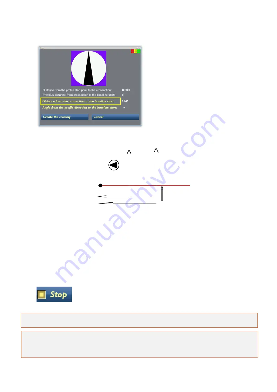
After pressing BL Crossing the
screen to the left is seen.
Here the current profile’s
positioning is defined, in terms of
distance from the baseline start
point and the direction of the
profile in relation to the baseline.
See the picture illustration below.
Key:
1: Orientation to baseline start point. In this case it is 270 degrees.
2: Distance from the start of the current profile to the baseline
3: Distance from baseline start to the current profile
4: Previous distance
First set the distance from the baseline start point to the current profile. Then select the angle of
the profile to the baseline start point. Finally, select Create the crossing, the screen reverts back
to the measurement screen and a blue marker dot is seen on the GPR profile. Continue the
measurement along the current profile.
Once a profile is completed, select Stop; the Start Profile screen will be
seen and a new profile can be started as usual, again applying the BL
Crossing option when passing the baseline.
Note: The GX Controller and the ObjectMapper project will automatically suggest the distance
and the angle to the baseline start after 3 passes of the baseline.
Tip: Moving in the opposite direction after each profile is finished (i.e. “zig-zag”) can optimise
data collection. If measuring every second profile in the opposite direction and at a right angle to
the baseline the angle from the profile direction to the baseline start will be 270, 90, 270, 90 and
so on.
1
3
1
2
4
Baseline end
Measured
GPR Profiles
Baseline
start
1
3
1
2
4
Baseline end
Measured
GPR Profiles
Baseline
start


