background image

l


18

Display Views

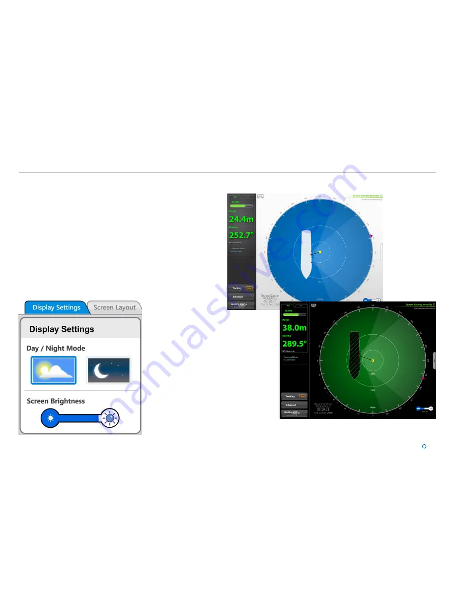
To provide ample visibility during daytime operation and to limit glare during night shifts, 
the Dashboard offers two display settings: Day Mode and Night Mode. In either mode the 
brightness can be further adjusted by the Screen Brightness control.

To change the day/night mode and adjust brightness:

1.  Navigate to 

Advanced 

Display Options

 > 

Display Settings

.

2.  Click on one of the 

Day/Night Mode

 symbols.

3.  Click on the left side of the 

Screen Brightness

 control to dim the screen and on the 

right to make it brighter.

Night Mode

Day Mode

Alternatively, to toggle between day and night mode, use the keyboard shortcut 

F6

 or 

the 

Toggle Day/Night Mode

 button in the Dashboard Hotkeys panel

Summary of Contents for RangeGuard Monopole

Page 1: ...ridian Business Park Leicester LE19 1QP UK www guidance eu com T 44 116 229 2600 E sales guidance eu com www marine direct RangeGuard Monopole Operator s Guide W A R R A N T Y See our standard terms o...

Page 2: ...idance Marine Ltd Windows is a trademark of Microsoft Corporation All other brand or product names are trademarks or registered trademarks of their respective companies or organisations Serial No Date...

Page 3: ...l 3 Document History Document Number Changes Issue Date 94 0522 4 A RangeGuard Monopole Operator s Guide 02 12 2016...

Page 4: ...To Stop Tracking 24 Positional Display Modes 25 Range Bearing 25 Bow and Starboard Axes 25 Multi Dashboard Systems Dashboard In Command Mode 27 Dashboard Monitoring Mode 28 Support Information Serial...

Page 5: ...following pages Welcome Page 6 System Overview Page 7 Note that whilst we endeavour to describe system functionality correctly in this document we do not guarantee that it exactly represents the versi...

Page 6: ...nd running and how to shut it down again It also details what you will see on the Dashboard screen when the system is running and how to interpret the information The Tracking Basics section on page 1...

Page 7: ...position of the monopole target System Overview RangeGuard Monopole Processing Unit The RangeGuard Monopole Processing Unit takes the observed signal from the two sensors and uses this to calculate a...

Page 8: ...l 8 Getting Started This section covers the basics of using the RangeGuard Monopole system It contains the following pages Start Up and Shut Down Page 9 Screen Layout Page 10 Display Views Page 18...

Page 9: ...leaves the Dashboard open Exit Closes down the Dashboard without affecting the RangeGuard Monopole Processing Unit Start Up To Start the RangeGuard Monopole Dashboard 1 Ensure that the RangeGuard Mono...

Page 10: ...shboard screen is split into three distinct sections these are Main Screen and Bird s Eye View BEV see page 11 Side Bar see page 13 Menu Pane see page 15 Main Screen and Bird s Eye View BEV Menu Pane...

Page 11: ...see Installer s Guide The field of view FOV of each sensor is indicated by the shaded area radiating from each of the sensors When blanking is configured at short range the shaded areas are offset to...

Page 12: ...le Processing Unit During a tracking operation the symbol is steady and when manual logging is in progress it flashes Zoom Control Click on the left hand side of the control marked to zoom out of the...

Page 13: ...l 13 Screen Layout Continued Side Bar The Side Bar the black pane to the left of the BEV contains control and display components in addition to the coordinates pane After pressing the Guidance button...

Page 14: ...out mode F5 Toggles between enlarged and standard sized reflections F6 Toggles between the day view and night view F7 Toggles between the About System pane and the full BEV display F10 Capture a scree...

Page 15: ...oot of the Side Bar are pressed This causes the Main Screen to contract towards the top of the screen Clicking the same button for a second time causes the Menu Pane to disappear and the Main Screen t...

Page 16: ...automatically reverts to Bird s Eye View but as long as Coordinates View remains selected the main screen will again display coordinates once the next tracking operation commences To Select Coordinat...

Page 17: ...ation one just for the current Dashboard session and the other which will apply to all Dashboards in the system and will persist after a Dashboard has been closed and re opened To set Default Vessel O...

Page 18: ...ghtness control To change the day night mode and adjust brightness 1 Navigate to Advanced Display Options Display Settings 2 Click on one of the Day Night Mode symbols 3 Click on the left side of the...

Page 19: ...ystem prior to tracking a target and describes information presented to the user whilst tracking is in progress It contains the following pages Working with Reflections Page 20 Tracking Information Qu...

Page 20: ...on the BEV Clicking on the target has the same effect as clicking on the target on the BEV Type The type of reflection as follows Reflection A target signal has been detected and verified Reject A tar...

Page 21: ...elected the Data Quality and Coordinates area in the upper left corner of the screen is grey After tracking has started the coordinates are displayed in green and the quality bar is largely filled If...

Page 22: ...uard Service Interface refer to 92 0523 4 A RangeGuard Monopole Installer s Guide The Dashboard contains a read only menu pane that displays the state of the DP output channels which DP format is conf...

Page 23: ...erial covered in this section will vary according to the type of DP system used in conjunction with the RangeGuard Monopole system The use of or reliance on anything in this section is therefore entir...

Page 24: ...er 1 superimposed Alternatively click on the target reflection on the Bird s Eye View or the Reflections menu pane 2 Click on the Apply button to confirm and begin tracking To Stop Tracking Whilst tra...

Page 25: ...priate tab above the Data Quality area Range Bearing Range and Bearing mode displays the distance and the bearing of the target from the tracking reference point The radial markers around the outside...

Page 26: ...Multi Dashboard Systems This section contains the following pages Dashboard In Command Mode See page 27 Dashboard Monitoring Mode See page 28 l 26...

Page 27: ...differently on each individual Dashboard whether it is Monitoring or In Command If there are no Dashboards in command of a RangeGuard Monopole system the next Dashboard to connect will automatically...

Page 28: ...disabled A Monitoring Dashboard displays the same reflections and positional data as the In Command Dashboard but it cannot initiate or stop target tracking and manual data logging Example of inactiv...

Page 29: ...ages Serial Numbers and Software Versions Page 30 Data Logging Page 32 Using the On Screen Keyboard Page 34 Working with Alarms Page 35 International Standards Compliance Page 37 System Specifications...

Page 30: ...rd Monopole System Serial Numbers and Software Version Numbers are used to identify the hardware configuration and product revision of each RangeGuard Monopole System They will be requested by Guidanc...

Page 31: ...Sensor Serial Number Serial Numbers and Software Versions continued Product Labels Part Numbers and Serial Numbers can be found on the product labels fixed to the rear of the processing unit and sens...

Page 32: ...as a short term measure for diagnosing a particular problem but in general the box should be left un ticked in order to conserve disk space To Enable Extended Data Logging 1 Navigate to Advanced Data...

Page 33: ...Start Manual Data Log buttons Exporting Data Logs The most recent data logs can be exported to a remote drive on the Dashboard computer To Export Data Logs 1 Insert a USB or other removable drive into...

Page 34: ...keyboard then it will already be enabled Otherwise click F11 or the Enable On Screen Keyboard button in the Dashboard Hotkeys menu To use the on screen keyboard Simply click on any text entry field an...

Page 35: ...button to toggle between activated and de activated Click on the Filter Selection button to choose which types of alarm are to be filtered out A tick means that alarms of the corresponding severity a...

Page 36: ...ms Tab 1 Click on Advanced Alarms and ensure that the Current Alarms tab is in focus 2 Select the alarms that you wish to move into the Historic list To accept one alarm Click on the alarm and click o...

Page 37: ...EU member states without the need for a specific administrative licence The RangeGuard K Band Sensor meets the R TTE Directive The equipment complies with EN 60945 2002 USA Use of the RangeGuard syst...

Page 38: ...nominal 100W I O Sensor to Dashboard Ethernet 100Base T Sensor to DP RS422 9600 to 115200 baud Data Formats RangeGuard Monopole Tracking DP feed format Control data Display Operating System Windows 7...

Page 39: ...Atmospheric Conditions 38 Azimuth Beam Width 38 B Bearing Tags 12 Bird s Eye View BEV 10 11 Bow Axis C Command Mode In Command 27 Monitoring 28 Coordinate Data 16 Coordinates View 16 D Dashboard Overv...

Page 40: ...7 Screen Layout 10 Screenshot 33 Secondary Status Display 12 Sensor Overview 7 Serial Numbers 30 Side Bar 13 Software 30 Software Versions 30 Standards 37 38 Starboard Axis 25 Start Manual Data Loggin...

Page 41: ......

Reviews: