background image

Guidance Marine Ltd, 4 Dominus Way, Meridian Business Park, Leicester LE19 1RP, UK 

www.guidance.eu.com

T: 

+44 116 229 2600

  E:

 [email protected] 

www.marine.direct

RadaScan Installer’s Guide

W

A R

R A N

T

Y

See o

ur standard terms

 of 

sa

le

Q

U

AL

ITY

 ASSUR

ED

3

YEAR

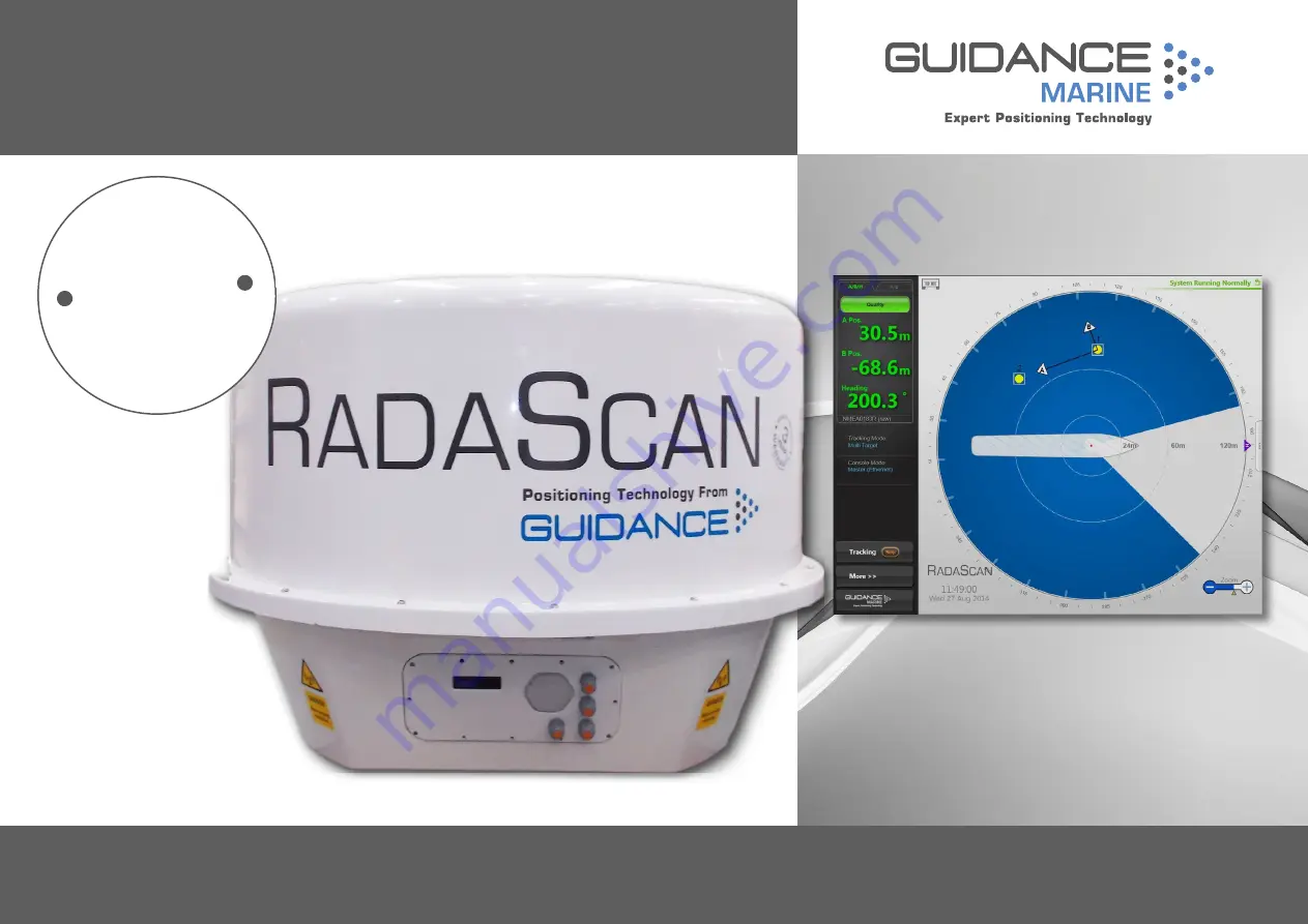
featuring  RadaScan  

Dashboard 

Guidance Marine Ltd, 5 Tiber Way, Meridian Business Park, Leicester, LE19 1QP, UK

T: +441162292600      E: [email protected]

Summary of Contents for RadaScan View

Page 1: ...4 116 229 2600 E sales guidance eu com www marine direct RadaScan Installer s Guide W A R R A N T Y See our standard terms of sale Q U A LITY ASSURE D 3 YEAR featuring RadaScan Dashboard Guidance Mari...

Page 2: ...Marine Limited the Owner and may not be used sold transferred copied or reproduced in whole or in part in any manner or form or in or on any media to any person other than in accordance with the terms...

Page 3: ...0394 4 A First release of RadaScan Dashboard Installer s Guide 23 12 2014 94 0394 4 B New DIN rail assembly new radome and Series 3 responders 19 11 2015 94 0394 4 C New standard sensor connections d...

Page 4: ...ptions 25 Sensor Information Display 26 Installing the Sensor Software 28 Installing the Type 2 Marine Processor Type 2 Marine Processor Dimensions 30 Plan view 30 Type 2 Marine Processor Connections...

Page 5: ...ides an introduction and overview of the RadaScan system It contains the following pages Welcome page 6 System Overview page 7 Important Safety Notes page 8 Serial Numbers and Software Versions page 1...

Page 6: ...to the RadaScan Type 2 Marine Processor and the vessel s DP system It also explains how to upgrade the sensor software if required The Installing the Type 2 Marine Processor section on page 29 gives r...

Page 7: ...s DP system and to the RadaScan Dashboard System Overview RadaScan Dashboard Software The RadaScan Dashboard software runs on a marine specification processor usually mounted on the bridge near to the...

Page 8: ...ome when the unit is operational Risk of Electric Shock Disconnect the mains electricity supply before opening the connection panel or removing the radome cover Isolating the Sensor For PERMANENTLY CO...

Page 9: ...and fitting the washer and nut from below Figure 2 4 Tighten the nut using a torque of 30Nm 5 Repeat steps 1 4 to fit the other two lifting eyes 6 Securely attach the sensor to suitable lifting equipm...

Page 10: ...are used to identify the hardware configuration and product revision of each RadaScan sensor They will be requested by Guidance Marine in the event of an application service or support call to the com...

Page 11: ...ns page 17 Mounting Template page 18 Standard Sensor Connections Direct page 19 Low Temperature Sensor Connections Direct page 20 Sensor Connections Separate Ethernet Connection Box 3 Glands page 21 S...

Page 12: ...vel as the responders that the vessel will be using Well above sea level to prevent swamping or immersion Allowing for easy access to the connection panel and Sensor Information Display On a different...

Page 13: ...separation of the two systems is impossible they must be shielded from one another with a metal screen The screen must be large enough to physically shield the RadaScan sensor from the whole width of...

Page 14: ...n panel facing towards the vessel s bow Connection panel faces away from the operating area The sensor s position Bow and Starboard Offsets and orientation Bearing Offset must be set up in the Dashboa...

Page 15: ...ection panel facing towards the vessel s stern Connection panel faces away from the operating area The sensor s position Bow and Starboard Offsets and orientation Bearing Offset must be set up in the...

Page 16: ...e line Connection panel faces away from the operating area The sensor s position Bow and Starboard Offsets and orientation Bearing Offset must be set up in the Dashboard Software RadaScan Sensor Respo...

Page 17: ...Sensor Dimensions 17 315mm 315mm 360mm 360mm Front Bottom 4 x M12 Mounting Holes Thread depth 30mm Min engagement 20mm Max engagement 25mm 1214mm 307mm 885mm...

Page 18: ...TO SCALE 315mm 360mm Mounting Plate Edge of Radome Four M12 Mounting Holes Custom made plinths must be flat rigid and horizontal They must be able to support 100kg and receive four M12 mounting bolts...

Page 19: ...hatch and replace the hatch Tighten all of the cable glands to ensure a watertight seal Inspection Hatch Cable Glands Radome E E N N L L SCR TX TX GND RS422 Link 9600 baud 8 bits 1 stop bit No parity...

Page 20: ...and gland 4 Connect the cable to the correct socket terminal inside the sensor 5 When all connections have been made apply DC4 compound around the seal of the inspection hatch and replace the hatch Ti...

Page 21: ...Processor LAN1 192 168 2 241 Subnet Mask 255 255 255 0 CAUTION Double Pole Neutral Fusing RadaScan Fuse Rating 2 x T4A H 250V OR 2 x T8A H 125V 5 x 20mm Connection Box Patch Cable Mains Power 115VAC...

Page 22: ...0A T 125V 2 x T12A T 240V all 6 3 x 32mm CAT 5e Cable CAT 5e Cable Heater Power Standard Sensor 115VAC 10A 800W OR 240VAC 7A 800W Low Temperature Sensor 115VAC 20A 1600W OR 240VAC 12A 1600W Mains Powe...

Page 23: ...and monitor options Emergency Breaker Box Ethernet Sensor Power RS 422 Data Monitor Power Cable Marine Processor Power Cable Power Cable P N 33 0123 3 40m Data Cable P N 33 0122 3 40m Ethernet Cable...

Page 24: ...0124 3 40m DP System UPS DP System Interface Cabinet Vessel s Main Power Supply Heater Power Heater Cable P N 33 0357 3 40m Connection Box Monitor Type 2 Marine Processor See page 24 for processor and...

Page 25: ...or Cable Power Adaptor Marine Processor Power Cable Hatteland Touchscreen Monitor Processor Type 2 Marine Processor Part Number 20 0157 0 Monitor Hatteland Marine Touchscreen Monitor Part Number 20 02...

Page 26: ...ot be paused If the display sticks on one screen the sensor has crashed and should be restarted Information Display Location The Sensor s Information Display VFD Screen is on the side of the sensor un...

Page 27: ...stall the sensor software see page 27 Second Stage boot Ver 3 5 1 144 Second Stage boot Ver 3 5 1 144 Operating System ver 3 5 1 144 Operating System ver 3 5 1 144 Starting Sensor Starting Sensor Rese...

Page 28: ...rea network as the sensor 2 Double click on the RadaScan Installer Remote exe file The RadaScan Installation Configuration screen is displayed 3 If the IP Address shown is not correct for your sensor...

Page 29: ...owing pages Type 2 Marine Processor Dimensions page 30 Type 2 Marine Processor Connections page 31 Installing the Dashboard Software onto a Type 2 Marine Processor page 32 Installing the Dashboard Sof...

Page 30: ...rine Processor rear view The computer running the RadaScan Dashboard should ideally be mounted on the bridge near to the controls of the vessel s DP system For customers using the Type 2 Marine Proces...

Page 31: ...w of Type 2 Marine Processor Part No 20 0157 0 Connect a sensor to the Marine Processor using either of the Ethernet ports the other may be used for diagnostics Rear View Front View Input from power a...

Page 32: ...he Uninstall button on the RadaScan Dashboard Setup window 6 When prompted click on the Restart button After the restart the RadaScan Dashboard Setup window reappears 7 When prompted click on the Rest...

Page 33: ...an Dashboard on a touchscreen monitor touch and hold 4 Click on the Uninstall option in the context menu 5 Click on the Uninstall button on the RadaScan Dashboard Setup window 6 Click on the Close but...

Page 34: ...uidance Navigation Ltd RadaScan RadaScan Dashboard config ini Note that on a Windows 64 bit computer the default location is C Program Files x86 Guidance Marine Ltd RadaScan RadaScan Dashboard config...

Page 35: ...tains the following pages Start Up and Shut Down page 36 Setting the Date and Time page 37 Using the On Screen Keyboard page 38 Entering Service Access Mode page 39 Configuration Settings page 40 DP M...

Page 36: ...t Communications Click on the Guidance button in the lower left corner of the screen The set of buttons revealed will depend on whether the Dashboard is running as a Master or Slave Each button is exp...

Page 37: ...en the Date Time pane The system s current date and time is displayed as a static value the Refresh button can be used to update this 2 Amend the contents of the date and time box and click Apply 3 Cl...

Page 38: ...e OSK can be enabled and disabled by clicking F11 or by clicking the Hotkeys tab and Enable On Screen Keyboard Disable On Screen Keyboard To use the on screen keyboard Simply click on any text entry f...

Page 39: ...ne and click on the Service Access Locked button The system will enter Service Access mode which will be available for the next 12 hours After 20 minutes it will automatically revert to normal access...

Page 40: ...u is open in the Side Bar close it by clicking on the Guidance button 2 Click on one of the Tracking or More buttons Further pages can be accessed by clicking on the tabs at the top of the Menu Pane A...

Page 41: ...configuration The following behaviour applies when tracking For all DP formats except for MT Custom DP Feed Always Enabled Allow Refresh Timer and Zero Strings Output when tracking and target is lost...

Page 42: ...e no effect The following behaviour applies when the system is suspended For all DP formats except for MT Custom DP Feed Always Enabled Allow Refresh Timer and Zero Strings Output when system is suspe...

Page 43: ...View Screen Layout By default the Tracking Coordinates Panel displays only one positional display mode e g Range Bearing If the selected DP message format supports a second mode e g A Pos B Pos Headin...

Page 44: ...sor to the vessel s starboard side in metres Vessel Parameters Bearing Offset This should be 0 if the RadaScan sensor is mounted exactly parallel to the vessel s centre line running from bow to stern...

Page 45: ...ontinued Starboard Offset Bow Offset RadaScan Sensor Port Side Starboard Side Bow and Starboard Offsets Enter the correct Bow and Starboard Offset values on the Vessel Parameters Pane see Vessel Param...

Page 46: ...icular to vessel centre line Bearing Offset 90 Sensor Facing Starboard Connection panel facing port Sensor perpendicular to vessel centre line Bearing Offset 90 180 90 90 0 Key Bearing Offset Enter th...

Page 47: ...To Define a Blanking Zone 1 Ensure that the Dashboard is in Master Mode 2 Enter Service Access Mode see page 39 3 Click on More Blanking Zones 4 Click on Show Handles 5 Click one of the blanking zone...

Page 48: ...l and maintain RadaScan Responders It contains the following pages Responder Overview page 49 Positioning Responders page 51 Mounting Responders page 52 Charging Responders page 54 Operating Responder...

Page 49: ...95 2 Primary Cell Responder Part No 20 0194 2 Narrow Beam Primary Cell Responder Part No 20 0196 2 The Mains Powered Responder is used with Responder AC DC power supply Part No 21 0377 2 Both types of...

Page 50: ...actory condition Responders are not intended to be repaired by the user They must only be repaired or serviced by Guidance Marine or by an approved service representative of Guidance Marine in accorda...

Page 51: ...tres above the vessel mounted Sensor 9 9On outside corners of the rig or platform to minimise the amount of metallic structure around them 51 Good Location Good angle of incidence Lower angle of eleva...

Page 52: ...Responder 1 Hook the foot of the responder underneath the knob on the bottom of the mounting plate See below 2 Rotate the responder backwards until it is held in place by its magnet against the mount...

Page 53: ...onders continued Responder Swivel bracket with 2 x U bolts Primary cell pack bracket Part No 21 0340 1 with 2 x thumb screws Bracket tail to provide additional support Primary Cell Pack Part No 21 031...

Page 54: ...harging To Charge the Responder Note Only use the supplied charger Only charge at ambient temperatures of 0 C to 45 C 1 Switch the responder off and unscrew the charging socket cap on the rear of the...

Page 55: ...day left For a mains powered responder the light should flash with an interval of 5 seconds For a primary cell responder the light indicates the state of the primary cell pack 1 flash in 5 seconds PCP...

Page 56: ...ppendices International Standards Compliance page 57 Part Numbers page 58 DP Message Types page 59 UPS and Cable Specifications page 63 Network Connection Troubleshooting page 64 Installation Checklis...

Page 57: ...ase contact Telenor Maritime Radio to obtain a licence Telenor Maritime Radio Radio Licensing Department N 1331 FORNEBU NORWAY Tel 47 22 77 43 50 Fax 47 22 42 70 72 Web www maritimradio no USA Use of...

Page 58: ...er Cable 40m 33 0123 3 Heater Cable 40m 33 0302 3 Data Cable 40m 33 0122 3 Ethernet Cable 40m 33 0124 3 Ethernet Connector Plug 80 0075 4 Responders Component Part Number Series 2 Responder Rechargeab...

Page 59: ...roduce different values for AAA AA and BBB BB for a given layout of responders and are therefore not interchangeable The message type selected on the RadaScan Dashboard must always match the message t...

Page 60: ...cimal 1 5 chars E Sequence identifier 1 char IIII I RadaScan 16 bit responder ID 1 5 chars S Status V oid A vailable or N avigating 1 char RRR R RR Range in metres 4 7 chars ZR ZRZR Range standard dev...

Page 61: ...ecimal 1 5 chars IIII I RadaScan 16 bit responder ID 1 5 chars S Status V oid A vailable and N avigating 1 char RRR R RR Range in metres 4 7 chars ZR ZRZR Range standard deviation in metres 4 chars BB...

Page 62: ...th bearing measured bow clockwise Character Index Description Format 0 1 ID nn 2 Space 0x20h X 3 9 Range m nnnn nn 10 Space 0x20h X 11 16 Bearing degrees nnn nn 17 Space 0x20h X 18 19 NMEA style check...

Page 63: ...age Range 220 245VAC for 230V systems Recommended fusing 6 3A Low Temperature 40 deg to 55 deg C Output power 1600W 2x800W Voltage Range 110 125VAC for 115V systems Recommended fusing 2 x 10A Voltage...

Page 64: ...e conducted to confirm the connectivity and integrity of the Ethernet link These are Ping the Type 2 Marine Processor to sensor Ping from service laptop to Marine Processor Test cabling with PEAK netw...

Page 65: ...guration Check Requirement Dashboard record of Sensor IP Address The SensorIP setting within the config ini file located in the Dashboard s installation directory matches the sensor s IP address This...

Page 66: ...cking a responder switch on the vessel s radio systems Ensure that RadaScan system does not suffer any loss of signal quality Ensure that the vessel s radio systems are not adversely affected by the R...

Page 67: ...Brackets 12 C Cable Routing Diagram Direct Connection 23 Separate Connection Box 24 Cable Specifications 63 Charging Responders 54 Configuration Tab 40 Configuring RadaScan Dashboard 35 Sensor IP Add...

Page 68: ...hernet 58 Positioning Responders 51 Power Cable 55 58 Product Label 10 PSV 14 R RadaScan Dashboard Software 7 RadaScan Sensor 7 Radio Licence 57 Responder 7 Charging 54 Mounting 52 53 Operating 55 Pos...

Page 69: ......

Reviews: