


Mi
nor
Moderate
Se
ve
re
Ra
re
Often
F
requent
A
B
C
D
E
F
G
H
I
J
K
L
M
1
4
10
1
2
3
The following should be
prevented:
Safety goal
(negation of the event)
P
robability of
occurrence
R
isk assessment (<
=
3
; 4-8; 9-20; >
2
0
Internal assembly
Special operating modes
N
o
rmal
operati
o
n
H
a
zard no.
Internal
commi
ssi
oni
ng
Internal disassembly
C
o
mmi
ssi
oni
ng at the
T
rai
ni
ng at the customer
T
ransport
A
ssembl
y at the customer
Application area
E
xtent of the
damage
C
a
tegory / P
L
r (S
IL) mi
ni
mal
Risk assessment / safety goals / protective measures / residual risks
1)
Solution suggested to the customer (cursive, Times New Roman)
Güdel solution (Arial)
S
a
fety requi
rement ful
fil
led [Y
/N
]
Operati
ng manual
Protective measures
(existing protective measures)
Danger
symbol
F
loor-mounted dri
ve axi
s
R
a
is
ed dri
ve axes
Recommendation to avoid residual risks
Hazard analysis / risk analysis
Customer:
Machine type: all modules with/without control system
Project no.:
Document no.:
A
ffected person(s)
C
o
rrespondi
ng operati
ng
mode
Triggering factor
Event
(worst case)
(without protective measures)
S
e
tup / C
hangeover
C
leani
ng
T
roubl
eshooti
ng / R
epai
r
Mai
n
tenance
Disa
sse
m
b
ly
D
is
posal
Source of danger
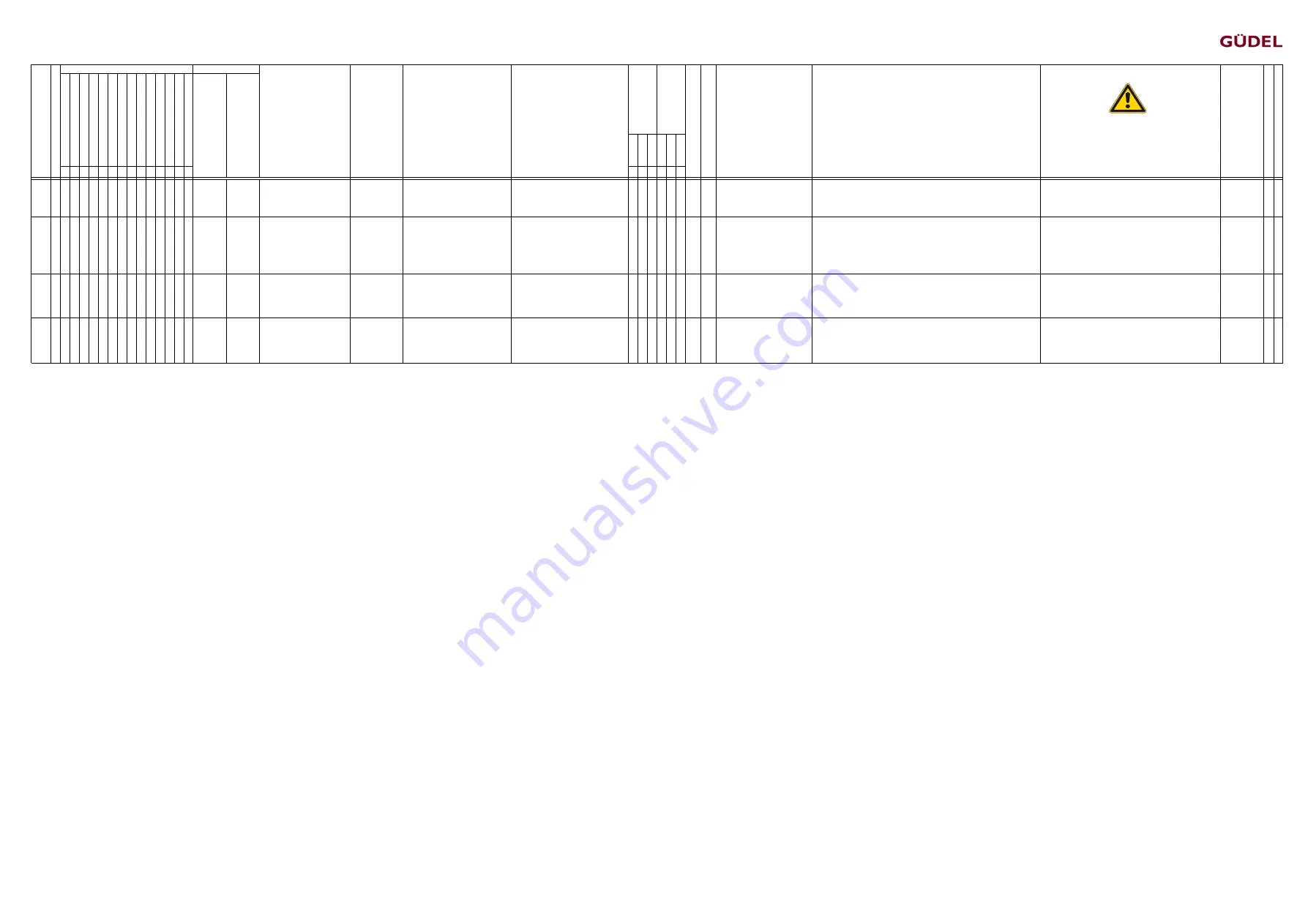
1.30 x
x
x
Malfunction of the control
system
Operator,
Maintenance
personnel
Failure of control unit components
Someone is surprised by the
unexpected movement and injured as
a result
x x
10 3/d The effects of a control system
malfunction endanger the
operator or third parties.
The areas of movement are to be enclosed by mechanical safety fences, light
curtains and light grids so that it is not possible to enter this area from any side.
Movements must transition to static states as quickly as possible.
In normal operation, all protective hoods must be closed,
removable protective hoods must be screwed securely.
Required conduct: Inspect the protective hoods before starting
normal operation.
x Y
1.31 x
x
x x x x x
x
x
Electrical hazard
Operator,
Maintenance
personnel,
Technicians
Touching the machine
Defective insulation
Improper el. installation
Unsuitable components
Someone suffers an electric shock and
is injured or killed as a result
x x
10 3/d Operating personnel or third
parties are injured by direct or
indirect electrical contact.
Only contact-protected components are to be used.
Before working on electrical installations, always disconnect the system (plug/main
switch) and double check.
Work on electrical installations, switch cabinets and devices may only be performed
by authorized technicians.
Control cabinet fuses
Work on electrical installations requires expertise and extra care.
x Y
1.32 x
x
x
Disruption of the energy
supply
Operator,
Maintenance
personnel
Power failure, lightning, interrupted
compressed air supply
Someone is surprised by the
unexpected movement and injured as
a result
x x
10 3/d The effects of a power failure
endanger the operator or third
parties.
The movement of the drives is mechanically limited in case the supply voltage fails
(mechanical limit stops and holding brakes).
The movement of the drives is braked if the supply voltage fails. The operator and
third parties are outside the danger area.
After a crash, defective elements of the mechanical limit stops
cannot necessarily be recognized immediately. The entire bumper
unit must always be replaced.
x Y
1.33
x
x
x
x
Disruption of the energy
supply
Setters
Power failure, lightning, interrupted
compressed air supply
Someone is surprised by the
unexpected situation and injured as a
result
x x
10 3/d The effects of a power failure
endanger the operator or third
parties.
The movement of the drives is limited by mechanical limit stops in case the supply
voltage fails. The drives have already been switched off in case of a power failure
(safety shutdown situation). The movement of the drives is braked in case of supply
voltage failure by the motor brake or holding brake in the drive train.
After a crash, defective elements of the mechanical limit stops
cannot necessarily be recognized immediately. The entire bumper
unit must always be replaced.
x Y
1)
Protective measures (comments):
The suggested solutions printed in italics are binding suggestions for achieving CE conformity.
We would like to point out, however, that before commissioning the plant, suitable protective measures must be implemented for all hazards to ensure CE-compliant use of the Güdel devices. According
to the CE Machinery Directive 2006/42/EC, these suitable protective measures, including all modifications, must comply with the "state of the art" and ensure the necessary safety category. If not all
protective measures are implemented for any reason or any protective measures supplied and/or installed by Güdel have been modified or not installed, Güdel will not commission the plant and will not
assume liability or provide a warranty relating to any resulting events.
Author: Alain Thurner
Created: 12/11/2009
Process owner: Martin Knuchel
Released: 16.03.2018 / Version 34
Page 3 of 3
Risikobeurteilung_EN_V34.xlsx
Summary of Contents for ZP 3-5 V4
Page 16: ...Table of contents OPERATING MANUAL ZP 3 5 V4 72057594174110603_v5 0_EN US 16...
Page 46: ...Transport OPERATING MANUAL ZP 3 5 V4 72057594174110603_v5 0_EN US 46...
Page 140: ...Commissioning OPERATING MANUAL ZP 3 5 V4 72057594174110603_v5 0_EN US 140...
Page 142: ...Operation OPERATING MANUAL ZP 3 5 V4 72057594174110603_v5 0_EN US 142...
Page 226: ...Maintenance OPERATING MANUAL ZP 3 5 V4 72057594174110603_v5 0_EN US 226...
Page 228: ...Maintenance OPERATING MANUAL ZP 3 5 V4 72057594174110603_v5 0_EN US 228...
Page 230: ...Maintenance OPERATING MANUAL ZP 3 5 V4 72057594174110603_v5 0_EN US 230...
Page 234: ...Maintenance OPERATING MANUAL ZP 3 5 V4 72057594174110603_v5 0_EN US 234...
Page 236: ...Maintenance OPERATING MANUAL ZP 3 5 V4 72057594174110603_v5 0_EN US 236...
Page 238: ...Maintenance OPERATING MANUAL ZP 3 5 V4 72057594174110603_v5 0_EN US 238...
Page 240: ...Maintenance OPERATING MANUAL ZP 3 5 V4 72057594174110603_v5 0_EN US 240...
Page 242: ...Maintenance OPERATING MANUAL ZP 3 5 V4 72057594174110603_v5 0_EN US 242...
Page 274: ...Repairs OPERATING MANUAL ZP 3 5 V4 72057594174110603_v5 0_EN US 274...
Page 280: ...Decommissioning storage OPERATING MANUAL ZP 3 5 V4 72057594174110603_v5 0_EN US 280...
Page 286: ...Spare parts supply OPERATING MANUAL ZP 3 5 V4 72057594174110603_v5 0_EN US 286...
Page 292: ...Spare parts supply OPERATING MANUAL ZP 3 5 V4 72057594174110603_v5 0_EN US 292...
Page 306: ...Illustrations OPERATING MANUAL ZP 3 5 V4 72057594174110603_v5 0_EN US 306...
Page 310: ...List of tables OPERATING MANUAL ZP 3 5 V4 72057594174110603_v5 0_EN US 310...
Page 318: ...Index OPERATING MANUAL ZP 3 5 V4 72057594174110603_v5 0_EN US 318...
Page 320: ...Appendix OPERATING MANUAL ZP 3 5 V4 72057594174110603_v5 0_EN US...
Page 321: ...Hazard analysis Risk analysis Appendix OPERATING MANUAL ZP 3 5 V4 72057594174110603_v5 0_EN US...
Page 322: ...Appendix OPERATING MANUAL ZP 3 5 V4 72057594174110603_v5 0_EN US...
Page 327: ...Appendix OPERATING MANUAL ZP 3 5 V4 72057594174110603_v5 0_EN US...
Page 330: ...Technical data Appendix OPERATING MANUAL ZP 3 5 V4 72057594174110603_v5 0_EN US...
Page 331: ...Appendix OPERATING MANUAL ZP 3 5 V4 72057594174110603_v5 0_EN US...
Page 332: ...Layout Appendix OPERATING MANUAL ZP 3 5 V4 72057594174110603_v5 0_EN US...
Page 333: ...Appendix OPERATING MANUAL ZP 3 5 V4 72057594174110603_v5 0_EN US...
Page 334: ...Spare parts lists Appendix OPERATING MANUAL ZP 3 5 V4 72057594174110603_v5 0_EN US...
Page 335: ...Appendix OPERATING MANUAL ZP 3 5 V4 72057594174110603_v5 0_EN US...
Page 336: ...Options Appendix OPERATING MANUAL ZP 3 5 V4 72057594174110603_v5 0_EN US...
Page 337: ...Appendix OPERATING MANUAL ZP 3 5 V4 72057594174110603_v5 0_EN US...
Page 338: ...Third party documentation Appendix OPERATING MANUAL ZP 3 5 V4 72057594174110603_v5 0_EN US...
Page 339: ...Appendix OPERATING MANUAL ZP 3 5 V4 72057594174110603_v5 0_EN US...


