Mi
nor
Moderate
Se
ve
re
Ra
re
Often
F
requent
A
B
C
D
E
F
G
H
I
J
K
L
M
1
4
10
1
2
3
The following should be
prevented:
Safety goal
(negation of the event)
P
robability of
occurrence
R
isk assessment (<
=
3
; 4-8; 9-20; >
2
0
Internal assembly
Special operating modes
N
o
rmal
operati
o
n
H
a
zard no.
Internal
commi
ssi
oni
ng
Internal disassembly
C
o
mmi
ssi
oni
ng at the
T
rai
ni
ng at the customer
T
ransport
A
ssembl
y at the customer
Application area
E
xtent of the
damage
C
a
tegory / P
L
r (S
IL) mi
ni
mal
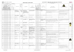
Risk assessment / safety goals / protective measures / residual risks
1)
Solution suggested to the customer (cursive, Times New Roman)
Güdel solution (Arial)
S
a
fety requi
rement ful
fil
led [Y
/N
]
Operati
ng manual
Protective measures
(existing protective measures)
Danger
symbol
F
loor-mounted dri
ve axi
s
R
a
is
ed dri
ve axes
Recommendation to avoid residual risks
Hazard analysis / risk analysis
Customer:
Machine type: all modules with/without control system
Project no.:
Document no.:
A
ffected person(s)
C
o
rrespondi
ng operati
ng
mode
Triggering factor
Event
(worst case)
(without protective measures)
S
e
tup / C
hangeover
C
leani
ng
T
roubl
eshooti
ng / R
epai
r
Mai
n
tenance
Disa
sse
m
b
ly
D
is
posal
Source of danger
1.13
x x x
x
Suspended loads
(vertical axes, telescope
axes, counter balance
cylinders, and workpieces)
Maintenance
personnel,
cleaning
personnel
Unexpected start-up
Defective motor brake
Torn belt (telescope axis)
Pressure drop (load balance)
General problems in the drive train
Disassembly of the vertical axis
motor
Person is surprised by unexpected
situation and injured as a result.
x x
10 3/d Persons injured by vertical axes
falling down.
Workpieces have to be deposited beforehand in automatic or setup mode.
The system must be brought into a safe state (emergency off).
Vertical axes have to be secured with the supplied locking pins for the vertical axes
or with the transport securing device.
Appropriate safety devices (cables, auxiliary supports etc.) must be used to secure
telescope axes against falling down.
Avoid walking under suspended workpieces or vertical axes. Take
special care with telescope axes. Inspect belts for cracks and tears
before every maintenance procedure.
Workpieces must be deposited beforehand in automatic or setup
mode.
Vertical axes must be secured with the supplied locking pins for
the
vertical axes or with the transport securing device.
Appropriate safety devices (cables, auxiliary supports etc.) must
be used to secure telescope axes against falling down.
x Y
1.14
x
x x x
x x x x x
x
x
Risk of injury (cutting,
crushing) gearbox, racks
Technician,
commissioning
technician,
forwarding agent
Carelessness
Cutting injuries, crush injuries
x
x
1
1/b Cutting and crush injuries occur
Wearing proper protective clothing
Application-specific protective measures
Y
1.15 x
x
x
x
x
x
Rotating parts
All
Contact with rotating parts
Persons are injured
x x
10 3/d Injuries occur
Attach protective cover or warning symbol
Wearing protective clothing
x Y
1.16 x
x
x
Manual workstations
Operators
Automatic movements at the
manual workstation
Someone is surprised by the
automation, body parts are crushed
and injuries result.
x
x
20 3/d Operating personnel or third
parties are injured during the
manual insertion or ejection of
the workpieces.
Insertion or ejection axes may only be moved in jog mode or with two-hand
operation. The drive configuration is such that only a slow axis speed is achieved at
maximum speed of the drive motor. The operating elements for insertion and
ejection must be configured so that the operator has a clear view of the movement
and cannot be endangered. Areas where body parts could be crushed are to be
prevented with design measures to the greatest possible extent.
Extra attention is required of the operator at manual workstations.
Only perform movements if no other person is in the danger area
and none of your own body parts are in the line of danger of the
corresponding axis
x Y
1.17 x
x x
x x x x x x x
x
x
Hot surfaces.
All
During normal operation,
touching hot surfaces.
Person is injured by hot surface.
x
x
8
2/c Persons suffer burns.
Hot surfaces are covered by mechanical protective devices or marked by the
operator.
None
x Y
1.18 x x x x
x x x x x x x x
x
x
Hot oil squirted out due to
high pressure at the gearbox
All
Overload or non-compliance with
the intended use
Burns or eye injuries
x x
10 3/d Oil comes out.
Use of the product within the defined parameters.
Wearing protective clothing, in particular helmet, goggles, and
shoes
x Y
1.19
x
x
x
x
x
No, wrong, or insufficient
oil
Technician,
maintenance
personnel
Improper oil change
Failure of the transfer function as well
as increased temperature, resulting in
damage and injuries
x x
10 3/d Consequential damage occurs,
with injuries
Maintenance instructions must be observed
None
x Y
1.20 x x x
x x
x x x x
x
x
Oil running out due to leaks
All
Failure of the gasket
Environmental damage, slipping
hazard as well as consequential
damage due to the insufficient oil (see
1.18)
x x
10 3/d The occurrence of
consequential damage with
injuries and environmental
damage
Maintenance intervals must be maintained
Application-specific protective measures
x Y
1.21 x
x
x
x x
x
x
Wear (tooth breakage)
gearbox
All
Tooth breakage
Transfer function fails, resulting in
consequential damage with injuries
x x
10 3/d Consequential damage occurs,
with injuries
Maintenance intervals must be maintained
Application-specific protective measures
x Y
1.22 x
x
x
x
x
Noise
All
Overload or non-compliance with
the intended parameters
Unpleasant noise level, difficult
communication
x
x
2
1/b Excessive noise level occurs
Use of the product within the defined parameters. Vibrations and resonances must
be prevented.
None
Y
1.23 x
x x x x
x
x
Malfunction of protection
measures
Operator,
Maintenance
personnel
Aging, fatigue fracture, failure due
to vibration or overloading
Someone is surprised by the
unexpected situation and injured as a
result
x x
10 3/d A preventable hazard occurs.
The plant is equipped with emergency stop devices that trigger an emergency stop of
the plant. A lock-out (overview of the switch off locations) draws attention to the
switch-off devices.
Do not walk under suspended workpieces or vertical axes. Only
possible in setup mode. Permanent workstations are not permitted
in the direction of movement of the axes.
x Y
1.24
x
x x x x x x x x
x
Slipping
All
Inattention and/or careless
operation
Persons are injured
x
x
4
2/c Injuries occur
For the option of walkable drive axes, use anti-slip plates.
Otherwise, walking on the drive axis is contrary to intended use.
None
x Y
1.25
x
x x x x x x x x
x
x
Danger of tripping
All
Inattention and/or careless
operation
Persons are injured
x
x
4
2/c Injuries occur
Customer must provide for sufficient protection in accordance with the ambient
conditions.
None
x Y
1.26
x
x
x
x
Faulty assembly
All
Incorrectly assembled plant
Someone is surprised by the
unexpected situation and injured as a
result
x x
10 3/d The module is mounted
incorrectly.
The content of the operating manual is known to the technicians.
Before a Güdel device is transported to the location of use, unpacked, assembled,
and commissioned, the operating manual must first be read and understood.
None
x Y
1.27
x
x
x
x
Loss of stability
All
Inattention and/or careless
operation
Machine/plant tips over
x x
10 3/d It is possible for the module to
tip or equipment to fall down.
Equipment without base supports:
To connect to customer supports, the specified screw configuration according to the
Güdel layout has to be used with the corresponding screws.
Equipment with base supports:
The supplied screws for assembly have to be used. For the connection of the
supports to the floor, the anchoring suggestion according to the Güdel layout needs
to be taken into consideration.
Fall protection has to be mounted for area gantries.
The operating manual must be read and understood.
Check the connections that are responsible for the stability of the
device before starting the plant.
x Y
1.28
x
x
x
Improper disposal can cause
environmental damage.
All
Disposal regulations are not
observed
Environmental hazard
x x
10 3/d The device and its
consumables are not disposed
of properly at the end of their
service life.
National regulations regarding disposal of the plant must be observed.
None
x Y
1.29
x
x
x
Malfunction of the control
system
Setters
Failure of control unit components
Someone is surprised by the
unexpected movement and injured as
a result
x x
10 3/d The risk of potential hazards
becomes too high.
Only drive systems are used that comply with the state of the art and the standards
referenced in the machine directive.
Work in this mode requires a high level of individual
responsibility from the operator/setter.
There is no way to completely ensure that a malfunction of the
control system does not create a hazard by moving the axes.
The operator must therefore try to never be in the possible
direction of travel of the axes and ensure that no third parties are
in the possible danger zones.
x Y
Author: Alain Thurner
Created: 12/11/2009
Process owner: Martin Knuchel
Released: 16.03.2018 / Version 34
Page 2 of 3
Risikobeurteilung_EN_V34.xlsx
Summary of Contents for ZP 3-5 V4
Page 16: ...Table of contents OPERATING MANUAL ZP 3 5 V4 72057594174110603_v5 0_EN US 16...
Page 46: ...Transport OPERATING MANUAL ZP 3 5 V4 72057594174110603_v5 0_EN US 46...
Page 140: ...Commissioning OPERATING MANUAL ZP 3 5 V4 72057594174110603_v5 0_EN US 140...
Page 142: ...Operation OPERATING MANUAL ZP 3 5 V4 72057594174110603_v5 0_EN US 142...
Page 226: ...Maintenance OPERATING MANUAL ZP 3 5 V4 72057594174110603_v5 0_EN US 226...
Page 228: ...Maintenance OPERATING MANUAL ZP 3 5 V4 72057594174110603_v5 0_EN US 228...
Page 230: ...Maintenance OPERATING MANUAL ZP 3 5 V4 72057594174110603_v5 0_EN US 230...
Page 234: ...Maintenance OPERATING MANUAL ZP 3 5 V4 72057594174110603_v5 0_EN US 234...
Page 236: ...Maintenance OPERATING MANUAL ZP 3 5 V4 72057594174110603_v5 0_EN US 236...
Page 238: ...Maintenance OPERATING MANUAL ZP 3 5 V4 72057594174110603_v5 0_EN US 238...
Page 240: ...Maintenance OPERATING MANUAL ZP 3 5 V4 72057594174110603_v5 0_EN US 240...
Page 242: ...Maintenance OPERATING MANUAL ZP 3 5 V4 72057594174110603_v5 0_EN US 242...
Page 274: ...Repairs OPERATING MANUAL ZP 3 5 V4 72057594174110603_v5 0_EN US 274...
Page 280: ...Decommissioning storage OPERATING MANUAL ZP 3 5 V4 72057594174110603_v5 0_EN US 280...
Page 286: ...Spare parts supply OPERATING MANUAL ZP 3 5 V4 72057594174110603_v5 0_EN US 286...
Page 292: ...Spare parts supply OPERATING MANUAL ZP 3 5 V4 72057594174110603_v5 0_EN US 292...
Page 306: ...Illustrations OPERATING MANUAL ZP 3 5 V4 72057594174110603_v5 0_EN US 306...
Page 310: ...List of tables OPERATING MANUAL ZP 3 5 V4 72057594174110603_v5 0_EN US 310...
Page 318: ...Index OPERATING MANUAL ZP 3 5 V4 72057594174110603_v5 0_EN US 318...
Page 320: ...Appendix OPERATING MANUAL ZP 3 5 V4 72057594174110603_v5 0_EN US...
Page 321: ...Hazard analysis Risk analysis Appendix OPERATING MANUAL ZP 3 5 V4 72057594174110603_v5 0_EN US...
Page 322: ...Appendix OPERATING MANUAL ZP 3 5 V4 72057594174110603_v5 0_EN US...
Page 327: ...Appendix OPERATING MANUAL ZP 3 5 V4 72057594174110603_v5 0_EN US...
Page 330: ...Technical data Appendix OPERATING MANUAL ZP 3 5 V4 72057594174110603_v5 0_EN US...
Page 331: ...Appendix OPERATING MANUAL ZP 3 5 V4 72057594174110603_v5 0_EN US...
Page 332: ...Layout Appendix OPERATING MANUAL ZP 3 5 V4 72057594174110603_v5 0_EN US...
Page 333: ...Appendix OPERATING MANUAL ZP 3 5 V4 72057594174110603_v5 0_EN US...
Page 334: ...Spare parts lists Appendix OPERATING MANUAL ZP 3 5 V4 72057594174110603_v5 0_EN US...
Page 335: ...Appendix OPERATING MANUAL ZP 3 5 V4 72057594174110603_v5 0_EN US...
Page 336: ...Options Appendix OPERATING MANUAL ZP 3 5 V4 72057594174110603_v5 0_EN US...
Page 337: ...Appendix OPERATING MANUAL ZP 3 5 V4 72057594174110603_v5 0_EN US...
Page 338: ...Third party documentation Appendix OPERATING MANUAL ZP 3 5 V4 72057594174110603_v5 0_EN US...
Page 339: ...Appendix OPERATING MANUAL ZP 3 5 V4 72057594174110603_v5 0_EN US...

