16
A. Shutoff and lockout all power (electrical, pneumatic and hydraulic).
B. Shut down conveying line.
C. Open the drive cover access panel.
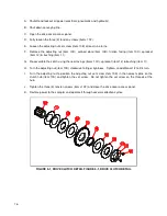
D. Fully loosen the three (3) tension screws (items 10F).
E. Loosen the adjusting nut set screw (item 10E) at least nine turns.
F. Remove the adjusting nut (item 10D), splined plate (item 10B), friction facing (item 10C), sprocket
(item 12) & bushing (item 11).
G. Re-assemble the clutch using the new facings (items 10C), sprocket (item 12) & bushing (item 11).
H. Turn the adjusting nut (item 10D) clockwise to finger tightness. Tighten an additional 1/2 to 3/4 turn.
I. Turn the adjusting nut to position the adjusting nut set screw (item 10E) in the nearest spline on the
clutch hub (item 10A) and tighten the set screw. Do not tighten the set screw on the threads of the
hub.
J. Tighten the three (3) tension screws (items 10F) and close the drive cover access panel.
K. Restore power to the sampler and operate it through several collection cycles.
FIGURE 5-1, DRIVE CLUTCH DETAIL FIGURE 5-1, DRIVE CLUTCH DETAIL

