background image

14 

5.3 Lubrication 
5.3.1  Drive Chain, Sprockets & Idler Shaft 

The  drive  chain,  sprockets  &  idler  shaft  have  been  greased  at  the  factory.    The  chain  should  be  thoroughly 

cleaned and re-greased once a year using a multi-purpose grease.  The idler shaft should also be greased at the 

same time. 


5.3.2  Gear Reducer 


The gear reducer is shipped filled with oil.  Check the oil level every six months and add oil if required.  Under 

normal sampler operating conditions the oil should be changed once every two years. 


Use a gear lubricant  with an AGMA #8 rating for normal operating conditions.  Use a synthetic gear lubricant such 

as "Mobil SHC 634" for extreme operating conditions. 


5.4  Mechanical Repair Procedures 
5.4.1  Drive Chain Adjustment 


The drive chain will need adjustment periodically to maintain proper tension.  The chain is attached to the sample 

pelican  drive  nose  by  means  of  two  eye  bolts.    Loosen,  adjust  and  re-tighten  the  eye  bolt  nuts  to  increase  or 

decrease chain tension.  The chain only needs to be tight enough to prevent any sag or slack.  As the chain wears 

it will stretch to a point where the adjustment of the eye bolts will no longer permit further tightening.  Shorten the 

chain by removing a link if necessary. 


5.4.2  Limit Switch Adjustment 


Loosen and adjust the limit switch arm if required.  The limit switches trip on the drive nose of the sampler and 

signal  the  control  to  remove  power  from  the  motor.    They  should  trip  before  the  sample  pelican  completes  its 

traverse.  When a limit switch trips the sample pelican should gently coast to a stop under the dust seal and up 

against the bumper. 


5.4.3  Sample Cutter Blade Replacement 


When following the instructions below, refer to the applicable drawing of the sampler.  Reference the drawing of 

the sampler on page 21 and the certified drawing(s). 


A.  Shutoff and lockout all power (electrical, pneumatic and hydraulic). 


B.  Shut down conveying line. 


C.  Open the seal door near the sample cutter. 


D.  Remove the 1/4-20UNC hex head bolts fastening the sample cutter to the sample pelican. 


E.  Using a utility knife, cut the caulking seal around the bottom of the cutter blade and remove. 


F.  Install the new cutter blade on the sample pelican. 


G.  Re-install the 1/4-20UNC hex head bolts fastening the sample cutter to the sample pelican. 


H.  Re-caulk the joint between the cutter blade and the sample pelican to ensure a tight seal. 


Summary of Contents for IS TD

Page 1: ...9575 N 109 th Ave Omaha Nebraska 68142 402 330 1500 www intersystems net SAFETY INSTALLATION OPERATION MAINTENANCE M A N U A L SAMPLER Model TD No PC 522818A Revised 2006 10 26...

Page 2: ...SE RIGHT Pilot Light 10 4 1 5 Digital Display Timer T 1 Standard 10 4 1 6 Main Fuse 11 4 1 7 Index Relay IR 1 11 4 1 8 Reverse Delay Timer Relays 12 4 1 9 Terminal Strip 12 4 2 Sampler Mounted Electri...

Page 3: ...RANTY 22 List Of Illustrations Drawings FIGURE 1 1 TD SAMPLER SAFETY LABEL LOCATIONS 4 FIGURE 2 1 TYPICAL INSTALLATION MODEL TD SAMPLING SYSTEM 5 FIGURE 4 1 STANDARD NEMA 12 CONTROL PANEL DETAIL 9 FIG...

Page 4: ...r its operating environment Careless changes could result in death or serious injury to people and reduce the performance and service life of the equipment Never perform any service on this equipment...

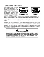
Page 5: ...4 FIGURE 1 1 TD SAMPLER SAFETY LABEL LOCATIONS...

Page 6: ...based but which could also be volume or quantity based A sample cycle begins when an electric motor drives the slotted sample cutter through the product flow to collect a sample of the material The s...

Page 7: ...of special materials such as stainless steel or nedox coatings D Programmable Controls to sequence the sampler and the sample collection equipment E Abrasion resistant linings of urethane AR carbon s...

Page 8: ...o be sampled as in Figure 2 1 Install the sampler as it is shown and noted on the certified drawings The sampler may or may not be supplied with a partial or a whole conveyor discharge hood Provide ne...

Page 9: ...O NOT locate the controller in a hazardous area D Most applications require that the sampler be in easy view of the controller 3 7 System Wiring Refer to the certified electrical drawing s for specifi...

Page 10: ...BY COMMON SENSE CAN RESULT IN DEATH SERIOUS INJURY AND OR EQUIPMENT DAMAGE LOCKOUT POWER BEFORE PERFORMING ANY MAINTENANCE 4 1 Control Components And Their Functions FIGURE 4 1 STANDARD NEMA 12 CONTRO...

Page 11: ...ly the timer begins timing down When the illuminated display reads all zeroes 000 the timer has timed out and initiates a sampling cycle The sample pelican traverses through the product flow to collec...

Page 12: ...d the timer is electronically switched to the new units as well 2 LINE FREQUENCY To set the proper line frequency connect the jumper wire to either the 50 HZ or 60 HZ pin These pins are clearly marked...

Page 13: ...mple cutter is in a rest position Upon initiation of a sample cycle the power is routed through the normally closed contacts of the opposite limit sample to the drive motor starter The drive motor sta...

Page 14: ...ed intervals while observing all safety precautions observe the sampler as it operates Inspect for A Loose or missing hardware B Noisy motor or motor reducer bearings C Overheated motor or reducer D A...

Page 15: ...oint where the adjustment of the eye bolts will no longer permit further tightening Shorten the chain by removing a link if necessary 5 4 2 Limit Switch Adjustment Loosen and adjust the limit switch a...

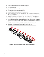
Page 16: ...clutch may need adjustment if it starts to slip When following the instructions below refer to the clutch drawing page 16 A Shutoff and lockout all power electrical pneumatic and hydraulic B Shut dow...

Page 17: ...ng the new facings items 10C sprocket item 12 bushing item 11 H Turn the adjusting nut item 10D clockwise to finger tightness Tighten an additional 1 2 to 3 4 turn I Turn the adjusting nut to position...

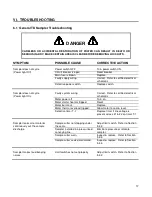
Page 18: ...rrect Refer to certified electrical schematic Motor power off Turn on Motor starter heaters tripped Reset Motor burnt out Replace Motor thermal overload tripped Allow motor to cool reset Defective tim...

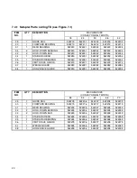
Page 19: ...lity built piece of machinery As with any machine parts do wear out and fail It is InterSystems recommendation that a small supply of spare parts be kept on hand to cover any minor breakdowns A separa...

Page 20: ...DJ LS LEVER ARM 2 18 35352 LIMIT SWITCH BRKT 2 19 35354 LIMIT SWITCH 2 20 35073 3 ID GUM RUBBER TUBE A R 21 SEE CERT DWG PELICAN DUST SEAL BRACKET 2 22 SEE CERT DWG SAMPLE PELICAN 1 23 SEE CERT DWG CU...

Page 21: ...2 522273 522274 37 1 WEDGE GUARD 522280 522281 522282 522283 522284 38 1 HORZ DRIVE GUARD 522290 522291 522292 522293 522294 ITEM NO QTY DESCRIPTION MACHINE SIZE CONVEYOR BELT WIDTH 48 54 60 66 70 29...

Page 22: ...21 FIGURE 7 1 TD SAMPLER PARTS DRAWING...

Page 23: ...r than by an Authorized Service Representative This warranty does not cover the replacement of parts inoperative because of wear occasioned by use the cost of replacing parts by a person other than an...

Reviews:

Related manuals for IS TD