12
4.1.8 Reverse Delay Timer Relays
These timers monitor the amount of time the sample
pelican takes to traverse from one side to the other and will
force the starter to reverse if the sample cutter takes too
long to complete its traverse. If the sample cutter fails to
traverse fully accross the material flow and trip the limit
switch prior to timing out the starter will reverse the motor
direction an return the cutter to the position it was at prior
to starting. The sample cutter is designed to travel at fixed
speed of 20 inches per second. Use the following chart
when setting the timer settings. Note an additional half
second was added to the theoretical traverse time to allow
for acceleration.
4.1.9 Terminal Strip
This 20-position barrier terminal strip serves as the controller's interface and connection point for all external
circuits and for the components mounted on the enclosure's front panel. Refer to the certified electrical
drawing(s).
4.2 Sampler Mounted Electrical Components
4.2.1 Limit Switches, LS-1 & LS-2
One of these switches is actuated when the
sample cutter is in a rest position. Upon initiation
of a sample cycle the power is routed through the
normally closed contacts of the opposite limit
sample to the drive motor starter. The drive
motor starts and the sample cutter traverses
through the material flow towards the other side.
Upon reaching the opposite side the limit switch is
tripped. The opening of the normally closed
contacts removes power to the drive motor starter
thus stopping the sample cutter rotation. The
sample cutter remains on this side until another
signal to sample is given by the controller.
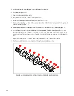
Correct wiring termination is essential to proper
sampler operation. Refer to figure 4-2, it shows
the limit switch utilized on the Exporter sampler
and the physical orientation of the proper wiring connections.
4.2.2 Drive Motor
This motor drives the sample cutter through a right angle gear reducer and a set of sprockets and chain. Verify
that the motor is turning the proper direction of rotation when wiring the system. On initial setup, jog the motor to
insure proper rotation.
MODEL
SIZE
STROKE
RECOMMENDED
DELAY TIMER SETTING
18
15
1.3 sec
24
21
1.6 sec
30
27
1.9 sec
36
33
2.2 sec
42
39
2.5 sec
48
49
3.0 sec
54
55
3.3 sec
60
61
3.6 sec
66
67
3.9 sec
72
73
4.2 sec
FIGURE 4-2, LIMIT SWITCH CONNECTIONS


