


Instrument Settings
The Corti instrument allows the user to change many of the
instrument's settings or functions. These settings include wireless
Device Pairing, Clearing Test Results, Auto Shutdown Time,
Minimum Amplitude Value, Save Mode, DPOAE Norms On/Off,
Clock Mode, Language, and Reset to Default Settings.
To access the menus to change these functions, press
CHANGE at
the main menu (Display 1) and then press
SETUP at the Protocol
Change (Display 2) to enter the Clock menu (Display 15). At the
Clock menu,
hold down
the
CHANGE key for 3 seconds until the
READY light (green LED) turns off and release the key.
NOTE:
Releasing the key will access the menus to change the
instrument settings.
Wireless Device Pairing
The wireless pairing menu (Display 18) allows the user to pair the
Corti unit with a wireless device, such as a thermal printer or personal
computer, for printing test results and data transfer.
The Corti unit can be paired to only one device; for example either
the thermal printer or a PC. To establish wireless pairing, turn on the
device that will be paired with the Corti unit (e.g.: thermal printer).
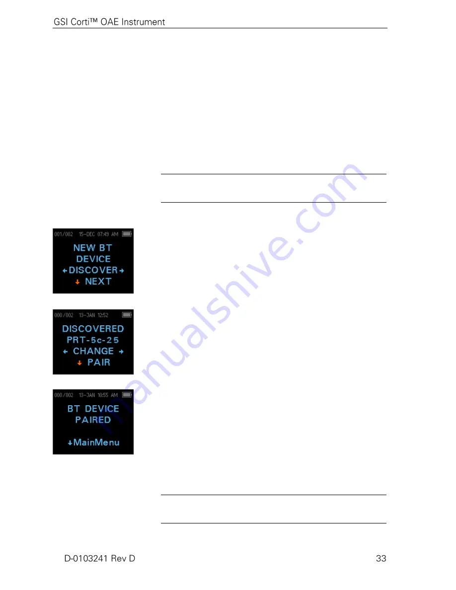
Follow the above instructions to access the menu in Display 18 then
select
DISCOVER
to initiate discovery of available wireless
devices. The Corti will search for available wireless devices for
approximately 15 seconds. The Corti will display the message
"Please Wait" and the yellow LED will flash.
When discovery is complete, all discovered devices are shown
(Display 19). A compatible thermal printer will appear as "
PRT-##-
##"
(example: PRT-5c-25) and other devices will be shown by their
name. Use the
CHANGE
buttons to find the desired device and
then use the
PAIR button to pair the Corti to the device.
For PC Pairing: On the PC, select Devices and Printers. Select
Add
a Device
. From the list of identified devices, select
OAE Device
.
Select and enter the pairing code
1234.
Select Next. A device driver
may be loaded automatically. The first time the Corti Data Manager
software is launched, select Detect Com Port to finalize the Corti
and PC wireless connection.
Pairing will be confirmed (Display 20). The pairing process is
complete. Select
Main Menu to exit the Wireless pairing menu.
NOTE:
See the Troubleshooting section on page 43 if wireless
pairing is unsuccessful or if any error messages are displayed.
Display 18
Display 19
Display 20


