background image

INSTALLATION

26

PNEG-1521

     Commercial Direct Gear Drive Bin Sweep Auger

10.  ASSEMBLING AND INSTALLING THE UNLOAD FLIGHT

(Cont.)

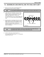
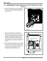
E. Insert the Unload Flight into the Unload Tube with

the Square bushing end facing the Centerwell,
and the Round bushing end facing the Discharge
End of the Tube.

Centerwell Square Shaft

Unload

Flight

FIG. 10-C

FIG. 10-B

F. When the Unload Flight is approaching the

Centerwell Square Shaft, it will be necessary to
rotate the Flight counter-clockwise to get it to seat
properly on the Square Shaft. When the Flight is
properly seated, the Flight should be entirely
inside the Unload Tube. It may be necessary to
pull the Flight out a small amount and attempt this
step multiple times in order to seat the Flight
properly.

G. On an initial install with an empty bin, the installer

should open the Centerwell Gate and enter the bin
to check and see that the Flight is seated.  Once
they have seen that it has seated, they will know
the proper position the Flight is in on the
Discharge End, when seated properly.

Summary of Contents for PNEG-1521

Page 1: ... Bin Sw Bin Sw Bin Sw Bin Swee ee ee ee eep p p p p A A A A Aug ug ug ug uger er er er er Assemb Assemb Assemb Assemb Assembl l l l ly y y y y Oper Oper Oper Oper Opera a a a ation Man tion Man tion Man tion Man tion Manual ual ual ual ual PNEG PNEG PNEG PNEG PNEG 1521 1521 1521 1521 1521 Date 08 19 10 Date 08 19 10 Date 08 19 10 Date 08 19 10 Date 08 19 10 PNEG 1521 ...

Page 2: ...ect Gear Drive Bin SweepAuger This manual is valid for the sweep catalog numbers in the table below Bin Dia 10 Commerical DGD Sweep 36 CPS10360 42 CPS10420 48 CPS10480 54 CPS10540 60 CPS10600 72 CPS10720 75 CPS10750 78 CPS10780 ...

Page 3: ...16 Outer Unload Tube Assembly Installation 17 18 Centerwell Control Gate Assembly 19 Bin Flange Installation 20 Rack Pinion Installation 21 22 Clutch Control Installation 23 24 Assembling and Installing the Unload Flight 25 26 Installing the Sweep Flighting 27 31 Sweep Wheel Installation 32 34 Motor Selection 35 Before Filling the Bin 36 Pre Start Checks 37 Normal Operation 38 39 Engaging the Clut...

Page 4: ...m the Transport Firm THIS MANUAL SHOULD BE CONSIDERED a permanent part of your equipment and should be easily accessible when needed WARRANTY is provided as part of the company s support program for customers who use and maintain their equipment as described in the manual The warranty is explained on the warranty page located on the inside of the back cover This warranty provides you the assurance...

Page 5: ...he equipment and may lead to serious injury or death DANGER indicates an imminently hazardous situation which if not avoided will result in death or serious injury This is the safety alert symbol It is used to alert you to potential personal injury hazards Obey all safety messages that follow this symbol to avoid possible injury or death WARNING indicates a potentially hazardous situation which if...

Page 6: ...nstallations are made OPERATE UNLOAD EQUIPMENT PROPERL Y Make sure ALL equipment is locked in position before operating NEVER start equipment until ALL persons are clear of the work area Be sure all operators are adequately rested and prepared to perform all functions of operating this equipment NEVER allow any person intoxicated or under the influence of alcohol or drugs to operate the equipment ...

Page 7: ...erstand any part of this manual and need assistance contact your dealer Read and Underst and Manual INSTALL OPERATE ELECTRICAL EQUIPMENT PROPERLY To avoid serious injury or death stay away from unit and make sure everyone is clear of all augers before starting or operating the unit Electrical controls should be installed by a qualified electrician and must meet the standards set by the national el...

Page 8: ...opriate to the job Safety glasses should be worn at all times to protect eyes from debris Wear gloves to protect your hands from sharp edges on plastic or steel parts A respirator may be needed if a hog house has poor ventilation Waste fumes can be toxic Wear hard hat and steel toe boots to help protect your head and toes from falling debris Remove all jewelry Tuck in any loose or dangling shoe st...

Page 9: ...d or incompetent persons are to remain out of work area 4 O S H A Occupational Safety Health Administration regulations state At the time of initial assignment and at least annually thereafter the employer shall instruct every employee in the safe operation and servicing of all equipment with which the employee is or will be involved Federal Occupational Safety Health Standards for Agriculture Sub...

Page 10: ...TANT BEFORE FILLING BIN CLOSE CENTER WELL AND INTERMEDIATE WELL GATES POSITION SWEEP AUGER OVER INTERMEDIATE WELLS INSTRUCTIONS 1 BE SURE POWER SWEEP CLUTCH CONTROL IS DISENGAGED AND TIGHTEN SET SCREW 2 START UNLOADING AUGER OPEN CENTER WELL GATE 3 WHEN GRAIN STOPS FLOWING FROM CENTER WELL GATE OPEN INSIDE INTERMEDIATE WELLS BEFORE OPENING OUTSIDE INTERMEDIATE WELLS 4 WHEN GRAIN STOPS FLOWING FROM...

Page 11: ...ation for people working near bin unloading equipment that is in operation KEEP OUT OF BIN WHILE SWEEP IS IN OPERATION RAPIDLY TRAVELING SWEEP AUGER FAILURE TO HEED WILL RESULT IN SERIOUS INJURY OR DEATH DC 1384 If the Safety Sign cannot be easily read for any reason or has been painted over replace it immediately Additional Safety Signs may be obtained free of charge from your dealer distributor ...

Page 12: ...oes not recommend setting the Direct Gear Drive Bin Sweep unit in concrete If installing a unit flush with a concrete floor we recommend the unit be installed in a preformed trench Use the diagram below 1 POWER SWEEPS IN BINS WITH CONCRETE FLOORS Center of Bin TOP VIEW SIDE VIEW CONCRETE TRENCH LA YOUT ...

Page 13: ... to complete assembly of the bin floor as the power sweep is being installed for better access to components under the floor B Locate the center of the bin and make a cut out in the bin floor for the Centerwell 2 POWER SWEEPS IN BINS WITH RAISED METAL FLOORS CENTERWELL CUT OUTAND LOCATION C Place the Centerwell into position with the vertical shaft between the two halves of the gearbox at the cent...

Page 14: ...50 48 4 23 10 1 2 39 863 57 25 322 388 35 888 54 4 26 10 1 4 47 113 64 50 358 388 36 138 60 5 29 10 1 8 42 363 59 75 394 138 36 013 72 6 35 9 3 4 44 113 61 50 465 638 35 888 75 6 37 3 5 8 46 613 64 00 483 638 36 013 78 6 38 9 9 16 49 113 66 50 501 638 36 075 DISTANCE FROM CENTER OF BIN TO WALL A NUMBER OF INTERMEDIATE WELLS BIN SIZE DISTANCE FROM BIN WALL TO ANGLE RING DISTANCE FROM CENTER OF BIN ...

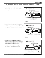
Page 15: ...dewall C On bins 60 in diameter place the angle ring end of the outer Unload Tube Assembly through the hole in the bin sidewall and then place the inner Unload Tube Assembly into place D Place the 12 Connecting Band onto the end of the Unload Tube Assembly closest to the Centerwell 4 UNLOAD TUBE ASSEMBLY INSTALLATION Centerwell Connecting Band Before installing the Unload Tube Assembly remove the ...

Page 16: ...gainst the Centerwell tube Unload Tube Centerwell Tube F Slide the Connecting Band until it is equally positioned over both the Unload Tube and the Centerwell tube Position the Connecting Band so that it will not interfere with the control rods G Secure the Connecting Band with three 3 5 16 x 1 Hex bolts and Serrated Flange nuts making sure the Intermediate Wells are level with the Centerwell FIG ...

Page 17: ...Wells are level with the Centerwell C Slide the Connecting Band until it is equally positioned over both the Unload Tube Assemblies Position the Connecting Band so that it is aligned with the keyways on the Unload Tubes D Secure the Connecting Band with eight 8 3 8 x 1 Hex bolts and Stover nuts Inner Unload Tube Outer Unload Tube Connecting Band Bolts and Nuts Removed CENTER OF BIN Inner Unload Tu...

Page 18: ...Control Rod 5 OUTER UNLOAD TUBE ASSEMBLY INSTALLATION Cont CENTER OF BIN Inside Intermediate Control Rod 1 External Control Pipe Coupler 1 2 Internal Control Pipe Coupler Centerwell Control Rod Centerwell Control Rods Inside Intermediate Control Rods FIG 5 D CENTER OF BIN FIG 5 E F Thread the other Centerwell Rod onto the coupler and leave it slightly loose Also thread the other Intermediate Rod o...

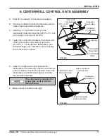
Page 19: ...n the Control Rod Clamp to the bottom side of the Centerwell Control Gate by using two 2 5 16 x Carriage bolts flat washers and Serrated Flange nuts Install the nuts so that they secure the roll pin in place Inside Intermediate Well Control Rod Holes are Aligned and Horizontal Centerwell Control Rod Outside Intermediate Well Control Rod E Adjust the Centerwell Control Rod and the Intermediate Cont...

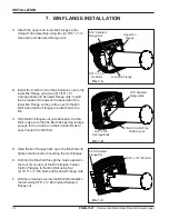
Page 20: ... Wall make sure that the Bin Wall opening is large enough for the Clutch and Well Control Rods to pass through the Bin Wall D Slide the Bin Flanges flush up to the Bin Wall and tighten the two bolts connecting the two Flanges E Drill into the Bin Wall through the holes located in the four 4 corners of the Bin Flanges Fasten the Bin Flanges to the Bin Wall using four 4 5 16 x Bin bolts and Serrated...

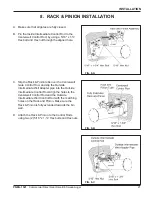
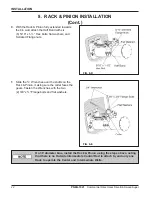
Page 21: ...ON C Slip the Rack Pinion tube over the Centerwell Gate Control Rod and slip the Outside Intermediate Well Adapter pipe into the Outside Intermediate Control Rod Align the holes to the Centerwell Control Rod and the Outside Intermediate Well Control Rod with the matching holes on the Rack and Pinion Make sure the Rack Pinion is fully extended towards the bin wall D Attach the Rack Pinion to the Co...

Page 22: ...uts F Slide the Wrenches over the shafts on the Rack Pinion making sure the collar faces the gears Fasten the Wrenches with the two 2 3 8 x Flange bolts and flat washers 8 RACK PINION INSTALLATION Cont On 36 diameter bins install the Rack Pinion using the steps above noting that there is no Outside Intermediate Control Rod to attach to and only one Rack to operate the Center and Intermediate Wells...

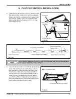
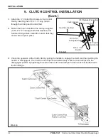
Page 23: ...nal Pipe Connector halfway onto the Rod attached to the Centerwell Bring the other Clutch Control Rod up to it by running the Rod through the Clutch Control Pipe Position Lock in the Bin Flange threaded end first and making sure that the Rod is contained by the Guides on the Intermediate Wells Then thread the Rod onto the remaining threads on the Coupler On 36 and 42 diameter bins the Clutch Contr...

Page 24: ...uts Install the nuts so that they secure the roll pin in place E Check the operation of the Clutch Rod by pulling the handle to engage the clutch and then pushing the handle to disengage it The Clutch Control Pipe should slide freely Lock the Control Pipe into the disengaged position by tightening the bolt on the Clutch Control Pipe Position Lock that is attached to the Bin Flange Clutch Handle 5 ...

Page 25: ...drilled holes Attach the 1 OD x 9 Connecting Shaft to the Inner Unload Flight using two 2 x 3 Grade 8 Hex bolts and Stover nuts C Align the Outer Unload Flight to the Inner Unload Flight making sure that the Dura Edge on both Flights are as continuous as possible the angle between both faces being less than 90 wherever possible but not greater than 180 and without overlapping Overlapping the Fligh...

Page 26: ...it will be necessary to rotate the Flight counter clockwise to get it to seat properly on the Square Shaft When the Flight is properly seated the Flight should be entirely inside the Unload Tube It may be necessary to pull the Flight out a small amount and attempt this step multiple times in order to seat the Flight properly G On an initial install with an empty bin the installer should open the C...

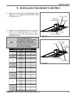
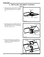
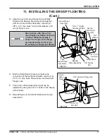
Page 27: ...he U Joint Flight Shaft to the U Joint using a 3 8 x 1 Square Key and a x 3 Hex bolt and Stover nut Tighten both setscrews after installation of keys Centerwell Gearbox Shaft 1 4 x 1 1 4 Key U Joint 3 8 Stover Nut U Joint 1 2 x 3 1 4 Hex Bolt U Joint Flight Shaft 3 8 x 1 1 2 Key 1 2 Stover Nut FIG 11 A FIG 11 B 3 8 x 3 Hex Bolt Bin Diameter Length Position from Center 6 10 1 8 4 2 9 10 1 4 1 8 4 2...

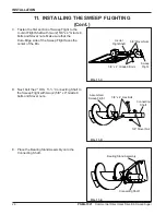
Page 28: ...two 2 5 8 x 4 Grade 8 bolts and Stover nuts Make sure that the Dura Edge side of the Sweep Flight faces the center of the Bin D Next bolt the 2 OD x 11 Connecting Shaft to the Sweep Flight with two 2 5 8 x 4 Grade 8 bolts and Stover nuts U Joint Flight Shaft 5 8 Stover Nuts 5 8 x 4 Grade 8 Bolts Sweep Flight Assembled Sweep Flight 5 8 x 4 Hex Bolt 5 8 Stover Nut Connecting Shaft Bearing StandAssem...

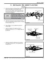
Page 29: ...d Nylock nut G Install the next section of Sweep Flight Bolt it to the Connecting Shaft using two 2 5 8 x 4 Grade 8 bolts and Stover nuts H Repeat Steps D G for additional sections of Sweep Flight I Attach the Gearbox Pivot Bracket onto the Gearbox with four 4 x 1 Flange bolts and flat washers Overlapping the Flights or having an angle between the ribbon faces be less than 90 or greater than 180 w...

Page 30: ...Shield to the Bearing Stand Assembly and the first section of Back Shield with two 2 3 8 x 3 Carriage bolts flat washers and Nylock nuts M Bolt the Shield Splice Plate to complete the connection of the two Back Shields Use four 4 5 16 x Hex bolts flat washers and Serrated Flange nuts 3 8 Nylock Nuts Flat Washer 3 8 x 1 1 2 Hex Bolt Flat Washers 3 8 Nylock Nut 3 8 x 3 Carriage Bolt Shield Splice Pl...

Page 31: ...Flange nuts P The Carrier Wheel Assembly height can be adjusted by using the 3 8 x 1 bolts on the Sweep Carrier Body Q Repeat Steps L M until all Shield sections are assembled Carrier Wheel Assembly 3 8 x 1 Height Adjustment Bolt Second Back Shield Assembly 3 8 x 3 1 2 Hex Bolt Flat Washer Bearing Stand Assembly Third Back Shield Assembly 5 16 x 3 4 Hex Bolt Flat Washer Shield Splice Plate 5 16 Se...

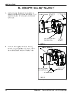
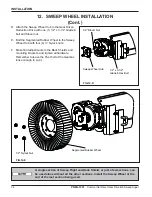
Page 32: ...shers and two 2 Nylock nuts 12 SWEEP WHEEL INSTALLATION B Attach the Mounting Bracket to the Housing Bracket using two 2 3 8 x 1 Grade 8 bolts two 2 flat washers and two 2 Nylock nuts FIG 12 A FIG 12 B Housing Bracket 1 2 x 4 1 2 Hex Bolt 1 2 Flat Washer 1 2 Nylock Nut Gear Driven Wheel Reduction Drive 3 8 Nylock Nut 3 8 Flat Washer 3 8 x 1 1 2 Hex Bolt Mounting Bracket with Anchor Loop ...

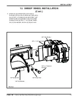
Page 33: ...iven Reduction Drive to the final Sweep Flight using two 2 5 8 x 4 Grade 8 bolts and Stover nuts Attach the Mounting Bracket to the Final Back Shield with two 2 3 8 x 1 1 2 Grade 8 bolts two 2 flat washers and two 2 Nylock nuts FIG 12 C 5 8 x 4 Grade 8 Hex Bolt 5 8 Stover Nut 3 8 Flat Washer 3 8 Nylock Nut 3 8 Flat Washer 3 8 x 1 1 2 Hex Bolt ...

Page 34: ...justments to the Back Shields and mounting brackets and tighten all hardware Remember to leave the Pivot bolt at the Gearbox loose enough to pivot A single section of Sweep Flight and Back Shield or just a few sections can be used alone without all the other sections Install the Sweep Wheel at the end of the last section being used FIG 12 D 12 SWEEP WHEEL INSTALLATION Cont FIG 12 E Sweep Wheel Hub...

Page 35: ... be locked out whenever work is being done on the Direct Gear Drive Bin Sweep 1 Electric motors and the controls should be installed by a qualified electrician and must meet the standards set by the National Electric Code and all state and local codes 2 A main power disconnect switch capable of being locked only in the OFF position shall be provided This disconnect shall be locked whenever work is...

Page 36: ...can easily fall and bury a person suffocating them DO NOTenter a bin with abnormal grain flow C With the power shut off and locked out enter the Bin and position the Sweep Auger along side of the Intermediate Wells D Where a Carrier Wheel Assembly is used adjust the height so that the Sweep Arm Assembly is close to the floor but WILL NOT contact the floor Intermediate Well Top Flanges or floor scr...

Page 37: ...first time make sure that all parts are assembled correctly according to the instructions in this manual Failure to perform any and all of these pre start checks may cause damage to the equipment and could cause SERIOUS INJUR Y or DEATH to those in the work area A failure to perform any and all of these pre start checks may also be a misuse of the equipment which may void the warranty ALWAYS keep ...

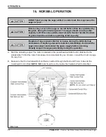
Page 38: ... any unusual vibration or noises during the initial start up and break in If anything unusual is detected immediately shut down the auger disconnect and lockout the power supply before servicing Visually inspect the auger periodically during the operation A Start the unloading auger The motor is located on the powerhead outside the bin attached to the unload tube To find the motor horsepower recom...

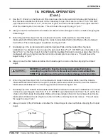
Page 39: ...w into the Centerwell will be at a higher rate than what the unload system can remove This will cause the auger to plug or jam G Always close the Well Gates and allow the Unload Auger to clean out before stopping the Unload Auger H When the grain flow stops from the Centerwell and Inside Intermediate Wells insert the Outside Intermediate Well Bolt and Nut through the Outside Intermediate Well Cont...

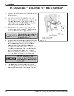
Page 40: ...position D Restore power and start the Unload Auger motor The Sweep Arm Augers will start being powered by the Unload Auger Each time the Auger is stopped it may be necessary to adjust the Sweep Carrier Wheel Assembly up or down so that the Arm is allowed to feed into the grain pile but also not come into contact with the floor Follow proper safety procedures before entering the bin to adjust the ...

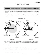
Page 41: ...ed Shortly the swept pile will have been CleanedArea Bin Wells Bin Wall SweepAuger 18 FINAL CLEAN OUT DO NOT enter a grain bin unless all power driven equipment has been shut down and locked out A After the Bin Sweep has made two passes removing most of the grain it will be necessary to clean the floor B With all power disconnected and locked out enter the grain bin Sweep or scoop the remaining gr...

Page 42: ...re everyone is outside of the bin and clear of the equipment K Start the Unload Auger with the Bin Sweep still engaged Shortly the swept pile will have been removed by the Bin Sweep Keep out of the bin while the Bin Sweep is in operation The Bin Sweep travels rapidly around the bin As the bin empties the Bin Sweep travels around the bin faster Stay clear of the Unload Auger under the floor at the ...

Page 43: ...k the power source 5 Clear the auger gradually until there is no grain and there are no obstructions C Storage Preparation 1 Close all wells to the discharge auger 2 Position the Direct Gear Drive Sweep along side the Intermediate Wells 3 Be sure the Unload Tube is empty 4 Shutdown the auger 5 Make sure all fasteners are tight NEVER start the equipment under load Doing so may cause damage This typ...

Page 44: ... ALL decals are legible and tightly attached to the equipment If necessary replace them FREE OF CHARGE by contacting the dealer warehouse or manufacturer E Mount controls for any electric motors at a safe distance from the machine and in a location accessible in case of an emergency F Make sure ALL electrical wiring is not damaged and that it meets proper wiring codes G Make sure ALL components ar...

Page 45: ... the intake should be covered with grain for maximum capacity B The auger is moving too slowly B1 Check the auger speed Low capacity will result from speeds slower thanrecommended 3 The auger plugs A The auger may be jamming because too much grain is reaching the auger B The motor may be too small or wired improperly B1 If the motor is a newer light weight aluminum type the next larger size may be...

Page 46: ... sure there is room for the auger to move Adjusting the shield may be necessary B Worn sweep wheel B1 The sweep wheel wears down over time Replace the wheel C Unconditioned grain C1 Moisture and or insects can cause the grain to harden or cake up Disconnect and lockout the power to the auger before going into the bin to correct this problem or to address any other problem Problem Possible Cause So...

Page 47: ...PARTS LIST 47 PNEG 1521 Commercial Direct Gear Drive Bin SweepAuger PARTS SECTION ...

Page 48: ...etail A 39 30 2 2 2 2 24 23 25 25 26 28 29 31 30 32 Detail C Detail B Detail D 27 13 2 2 6 5 6 10 6 2 6 9 8 9 9 21 20 29 9 2 6 6 29 40 41 1 17 7 14 7 7 7 7 11 9 19 34 18 15 9 16 15 17 29 42 See detail D See detail C See detail B See detail A 22 6 6 12 13 15 13 13 33 34 4 2 2 3 Well back plate is hidden for clarity ...

Page 49: ...23 15 Tooth Sprocket 1 1 4 Bore 60 w Keyway 19 S 8382 1 4 Square x 1 1 4 Key 20 GK7664 42P 60 Roller Chain 21 S 8618 Connecting Link 60 Roller Chain 22 S 7876 1 2 13 x 1 3 4 HHCS Bolt Zinc Grade 5 23 GK1702 Idler Sprocket Bracket 24 S 4108 5 8 11 x 2 3 4 HHCS Bolt YDP Grade 8 25 S 4307 5 8 Locking Collar 26 GK4941 11 Tooth Idler Sprocket 5 8 Bore 60 w Bearing 27 S 6494 5 8 11 Deformed Lock Nut Zin...

Page 50: ...lange Bearing w Lock Collar 4 GK7830 Bushing UHMW 1 1 2 Bore 5 GK7586 Clutch Jaw w Sprocket 1 1 2 Bore 60 17T 2 Bore 6 GK7587 Clutch Yoke Retaining Jaw 1 1 2 Bore w 3 8 Keyway 7 GK1330 1 1 4 2 Hole Flange Bearing w Lock Collar 8 GK7590 1 1 2 External Spiral Retaining Ring 9 S 9179 3 8 x 1 3 4 Square Key 10 S 8506 1 2 13 Serrated Flange Nut Zinc 11 S 9062 1 2 13 x 1 1 4 Flange Bolt Zinc Grade 5 Cen...

Page 51: ...t Zinc Grade 5 8 S 6076 5 16 18 x 3 4 Carriage Bolt Zinc Grade 2 9 S 7149 5 16 18 x 1 3 4 HHTB Bolt Zinc Grade 5 10 S 7382 5 16 18 Nylock Nut Zinc Grade 5 11 S 8382 1 4 Square x 1 1 4 Key 12 S 7249 3 8 16 x 3 HHCS Zinc Grade 5 13 GK7629 Gearbox Pivot Bracket 14 S 2121 1 2 Flat Washer Plated 9 16 I D x 1 10 x 1 3 8 O D 15 S 9062 1 2 13 x 1 1 4 Serrated Flange Bolt Zinc Grade 5 16 GK7630 Shield Pivo...

Page 52: ...PARTS LIST 52 PNEG 1521 Commercial Direct Gear Drive Bin SweepAuger INTERMEDIATE INSIDE WELL PARTS ...

Page 53: ...ediate Well Gate 4 GC09006 Control Pipe Clamp 1 5 GK6714 Clutch Control Pipe Guide 6 GK7571 Intermediate Well Top Flange 7 S 2741 5 16 18 x 1 1 2 HHCS Zinc Grade 5 8 S 1196 5 16 18 x 1 HHCS Zinc Grade 5 9 S 4275 5 16 18 x 3 4 HHTB Zinc Grade 5 10 S 3611 5 16 18 Serrated Flange Nut Zinc Grade 2 11 S 2121 1 2 Flat Washer Zinc 12 GC03064 1 2 O D x 5 8 Polyurethane Roller 13 S 7241 1 8 x 1 1 4 Cotter ...

Page 54: ...de C 7 S 8314 1 2 13 x 3 1 2 HHCS Zinc Grade 8 8 S 8315 1 2 Stover Nut Zinc Grade C 9 Unload Tube 10 Unload Flight SEE TABLE Connection Hardware Part Length Part Length Part Length Part Length 36 GK7593 223 50 GK7638 258 56 42 GK7594 269 25 GK7639 94 31 48 GK7595 305 00 GK7640 89 81 54 GK7596 341 00 GK7641 125 81 60 GK7597 376 75 GK7642 161 56 72 GK7615 192 25 GK7598 256 00 GK7643 233 06 75 GK7616...

Page 55: ...mediate Well Rack and Pinion Adapter 8 GK80080 42 78 Bin Outside Intermediate Rack Bar Body 9 GK80081 42 78 Bin Inside Intermediate Rack Bar Body GK80080 36 Bin Rack Bar Body 10 GC10316 Rack Bar 10P x 1 x 14 11 S 8999 5 16 18 x 1 2 HHCS Zinc Grade 5 12 GK7260 3 4 Wrench Assembly 13 S 2741 5 16 18 x 1 1 2 HHCS Zinc Grade 5 14 S 845 5 16 Flat Washer Zinc Grade 2 15 S 3611 5 16 18 Serrated Flange Nut...

Page 56: ...PARTS LIST 56 PNEG 1521 Commercial Direct Gear Drive Bin SweepAuger BIN FLANGE PARTS AND CONTROL PIPES ...

Page 57: ...harge End Intake End Control Pipes Clutch 16 GC11613 GC11606 248 00 95 00 Bin Dia 248 50 Discharge End Intake End N A 252 00 N A N A GK1776 GC11614 Ref Part Description GK7577 42 78 Bin Top Bin Flange Weldment GC10560 36 Bin Top Bin Flange Weldment 2 GC10558 10 Bottom Bin Flange Weldment 3 GK1619 Clutch Control Pipe Position Lock 4 GC01192 Clutch Control Pipe Handle 5 GK1726 Control Gate Clamp 1 2...

Page 58: ... 58 PNEG 1521 Commercial Direct Gear Drive Bin SweepAuger ASSEMBLED SWEEP ARM PARTS 3 7 6 10 11 13 14 12 15 9 13 14 13 2 5 8 11 13 15 4 1 10 13 23 17 20 23 18 10 19 15 9 10 22 21 10 19 11 11 13 16 11 15 11 21 22 ...

Page 59: ...PARTS LIST 59 PNEG 1521 Commercial Direct Gear Drive Bin Sweep Auger ASSEMBLED SWEEP ARM PARTS 25 15 18 17 11 20 13 23 23 13 22 22 26 24 10 10 21 26 13 11 10 13 16 11 15 21 ...

Page 60: ... 13 x 3 1 4 HHCS Zinc Grade 5 25 GK5162 Carrier Wheel Assembly 8 S 8315 1 2 13 Stover Nut Zinc Grade C 26 S 8676 3 8 16 x 3 1 2 HHCS Zinc Grade 5 9 GK5376 Flight Shield Bundle 27 GK2347 Mounting Bracket With Anchor Loop 10 S 7893 5 8 11 x 4 HHCS Zinc Grade 8 28 GK80022 Reduction Wheel Drive Gear 9 92 1 11 S 8606 5 8 11 Stover Nut Zinc Grade C 29 GK80049 Sweep Wheel Housing Bracket 12 GK7630 Shield...

Page 61: ...Carrier Body 2 GK5164 Sweep Carrier Leg Assembly 3 GK2085 Sweep W heel Disc 4 GC09726 Sweep Carrier W heel Bushing 5 GK5165 Sweep Carrier W heel Leg 6 S 7249 3 8 16 x 3 HHCS Zinc Grade 5 7 S 7383 3 8 Nylock Nut Zinc Grade 5 8 S 7469 3 8 16 x 1 HHCS Zinc Grade 5 Sw eep Carrier Assembly SWEEP CARRIER PARTS ...

Page 62: ... Idler Shaft 10 GK2354 Double Sprocket Assembly 50 40T 13T 11 GK2356 Sprocket 50 40T 1 14 Bore 12 GK4249 Sprocket 50 13T 1 Bore 13 GK2357 50 x 54P Chain 14 GK2358 50 x 46P Chain 15 S 236 1 2 Lock Washer Zinc 16 S 7932 1 2 13 x 3 4 HHCS Zinc Grade 5 17 S 1147 5 16 Lock Washer Zinc 18 S 396 5 16 Hex Nut Zinc Grade 2 19 S 6076 5 16 18 x 3 4 Carriage Bolt Zinc Grade 2 20 S 1054 3 8 Lock Washer Zinc 21...

Page 63: ...rs no cost to end user 3 to 5 years end user pays 25 5 to 7 years end user pays 50 7 to 10 years end user pays 75 Warranty prorated from list price 0 to 3 years no cost to end user 3 to 5 years end user pays 50 Motors burner components and moving parts not included Portable Dryer screens included Tower Dryer screens not included Conditions and Limitations THERE ARE NO WARRANTIES THAT EXTEND BEYOND...

Page 64: ...icable regulations which should be carefully followed in all cases Authorities having jurisdiction should be consulted before installation occurs Copyright 2010 by the GSI Group Printed in the USA 1004 E Illinois St Assumption IL 62510 0020 Phone 1 217 226 4421 Fax 1 217 226 4420 www gsiag com ...

Reviews: