INSTALLATION
27
PNEG-1521
Commercial Direct Gear Drive Bin Sweep Auger
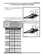
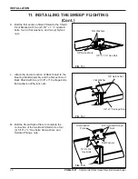
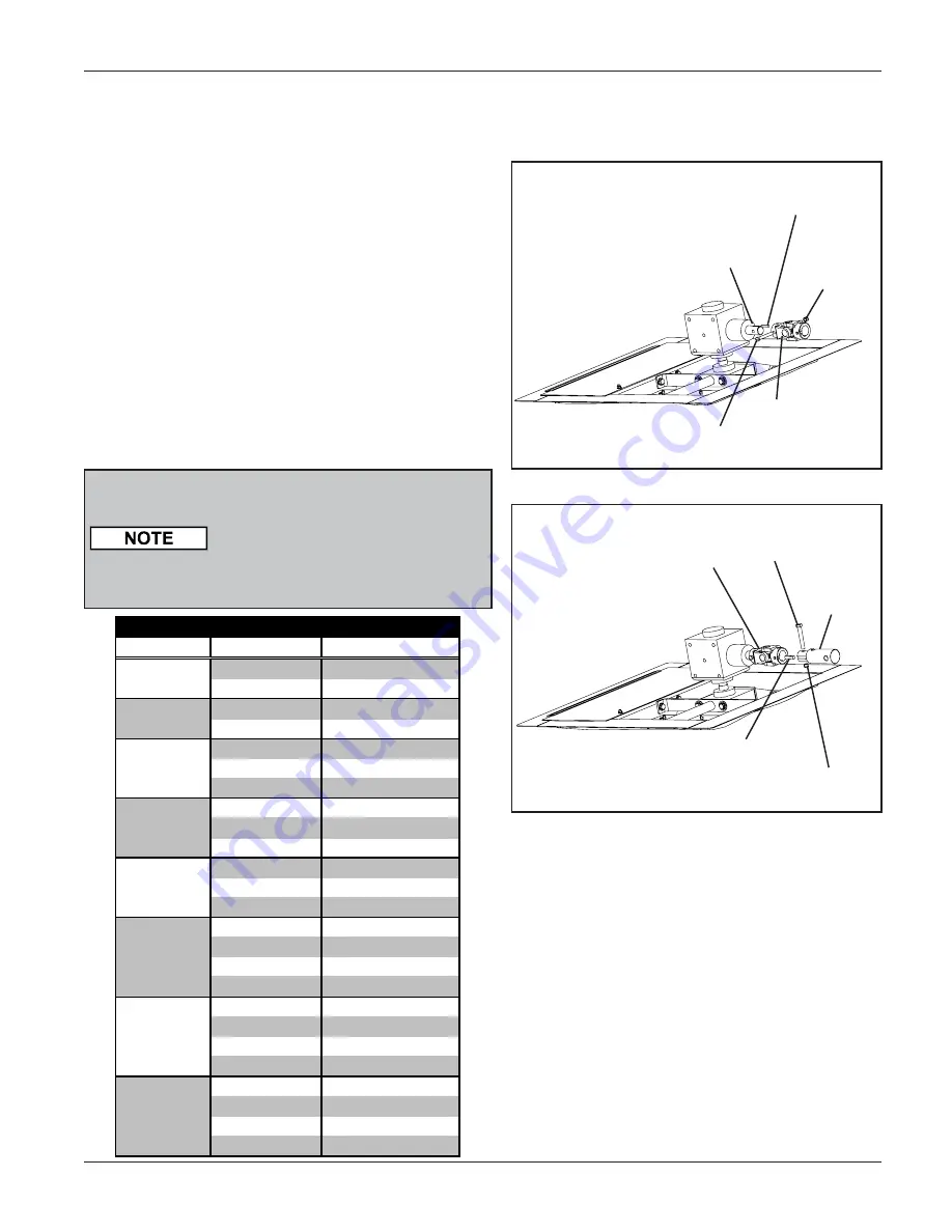
A. Attach the U-Joint to the Centerwell Gearbox Shaft
using a ¼” x 1-¼” Square Key, and a 3/8" x 3" Hex
bolt and Stover nut.
11. INSTALLING THE SWEEP FLIGHTING
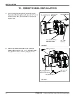
Use the table below to
determine the length, quantity
and position of the sweep
flights and back shields from
the center well to the wall, for
the given bin diameter .
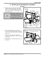
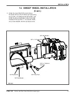
B. Attach the U-Joint Flight Shaft to the U-Joint using
a 3/8" x 1-½” Square Key, and a ½” x 3-¼” Hex
bolt and Stover nut. Tighten both setscrews after
installation of keys.
Centerwell
Gearbox Shaft
1/4” x 1-1/4” Key
U-Joint
3/8” Stover
Nut
U-Joint
1/2” x 3-1/4”
Hex Bolt
U-Joint
Flight Shaft
3/8” x 1-1/2” Key
1/2” Stover Nut
FIG. 11-A
FIG. 11-B
3/8” x 3” Hex Bolt
Bin Diameter
Length
Position from Center
6'-10"
1
8'-4"
2
9'-10-1/4"
1
8'-4"
2
6'-10"
1
8'-10-1/2"
2
5'-4"
3
9'-4"
1
9'-4"
2
5'-4"
3
8'-4"
1
9'-4"
2
9'-4"
3
8'-4"
1
8'-4"
2
6'-10"
3
9'-4"
4
8'-4"
1
8'-4"
2
8'-4"
3
9'-4"
4
8'-4"
1
9'-4"
2
8'-4"
3
9'-10-1/4"
4
Sweep Flights and Back Shields
36
42
48
78
52
60
72
75


