Grundig GRN-R5128N Owner'S Manual Download Page 26

9. Click the „Next“ button after you configured the network parameters, which takes you to the RAID Management 
window.

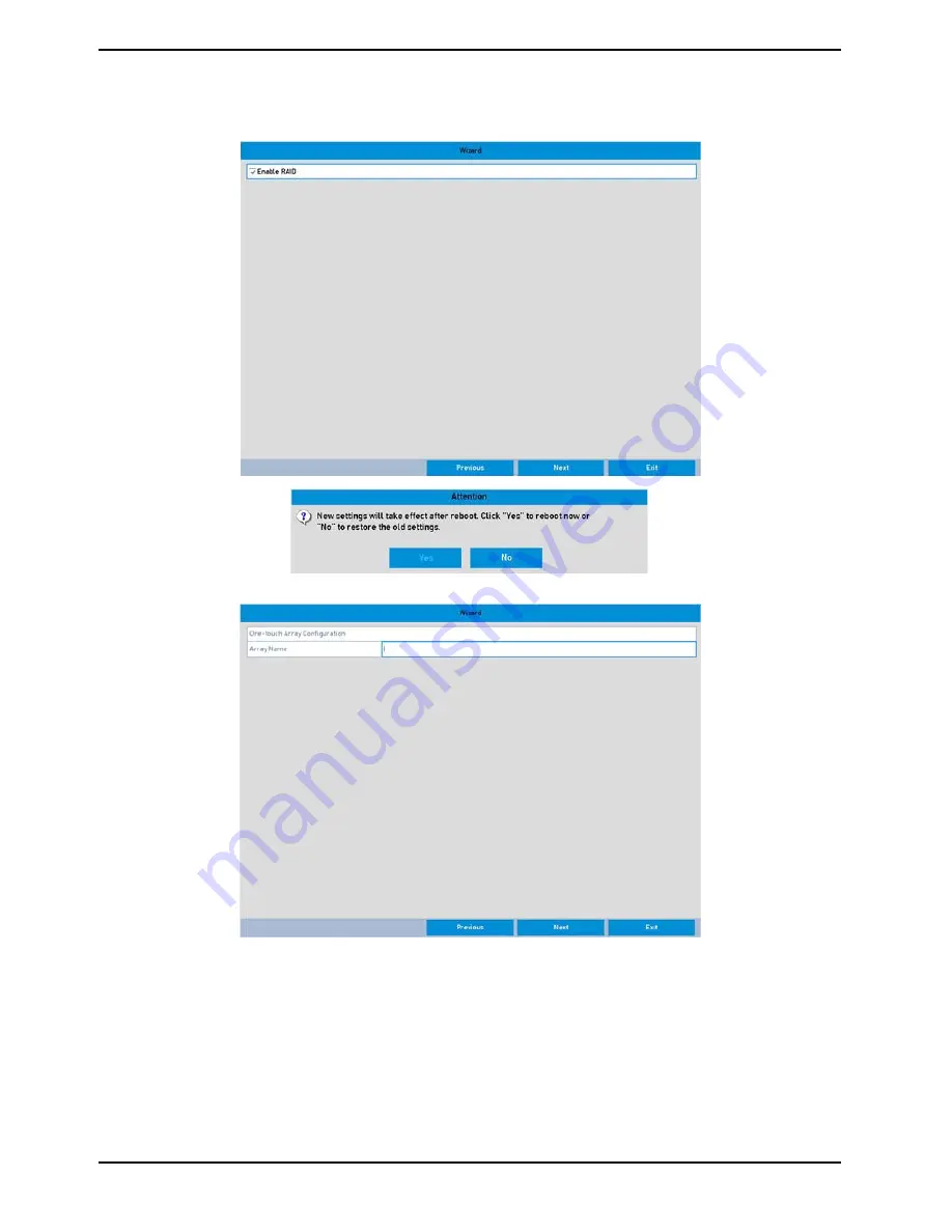
NOTE: If you enable RAID, the device needs to be rebooted.

10. Click "Next" to enter the Array Management Window.


11. Click the „Next“ button after you con

fi

gured the network parameters, which takes you to the HDD 

Management window.

26

English

Summary of Contents for GRN-R5128N

Page 1: ...GRN R5128N 195 1 16 05 2017 Owner s Manual ASP AG Recorders GRN R5128N 128 Channel NVR GRN R7256N 256 Channel NVR...

Page 2: ......

Page 3: ...nd Connecting IP Cameras 30 5 8 1 Add Online IP Cameras 30 5 8 2 Edit the connected IP Cameras and customised Protocols 34 6 Live View 37 6 1 Introduction of the Live View 37 6 2 Operations in Live Vi...

Page 4: ...of Playback 83 9 2 1 Playing Back Frame by Frame 83 9 2 2 Thumbnails View 83 9 2 3 Fast View 83 9 2 4 Digital Zoom 84 9 2 5 Reverse the Playback of Multi Channel 84 10 Backup 85 10 1 Backing up the R...

Page 5: ...135 13 5 Configuring the Quota Mode 137 13 6 Configuring the Disk Clone 138 13 7 Checking the HDD Status 138 13 8 HDD Detection 139 13 9 Configuring HDD Error Alarms 141 14 RAID Setup 142 14 1 Configu...

Page 6: ...156 17 Other Functions 157 17 1 Configuring the RS 232 Serial Port 157 17 2 Configuring the General Settings 157 17 3 Configuring the DST Settings 158 17 4 Configuring More Settings for the Device Par...

Page 7: ...problem in the NVR DVR The warranty period for the Fan is one year after purchase This product is not for exclusive use of crime prevention but also for assistance in cases of fire We take no respons...

Page 8: ...w screen can be switched to group view manual switch and automatic cycle live view are also provided and the interval of automatic cycle can be adjusted Quick setting menu is provided for live view Mo...

Page 9: ...0p real time Backup Exports video data to a USB SATA or eSATA device depending on model Exports video clips during playback Management and maintenance of backup devices Hot Spare working mode to act a...

Page 10: ...Product is for indoor use It is not weatherproof Please use the product considering its environmental specifications Temperature Humidity To clean the product gently wipe the outside with a clean dry...

Page 11: ...age Contents These parts are included 2x AC Cords 19 Brackets 32x SATA HDD slides 512x Screws for HDDs 1x Cat 6 Network Cable 1x eSATA Cable 1x Remote Control 1x Mouse 1x Setup CD 1x Quick Guide 11 En...

Page 12: ...4 Installation 4 1 Connections and Control Keys Front View 12 English...

Page 13: ...and shorten the product s life cycle Recommendations on installing a NVR DVR in a rack Do not seal the inside of the rack where the NVR DVR is installed Keep the airflow through the inlet and outlet...

Page 14: ...able must be removed for the HDDs previously used in a PC or other DVR models before installation Before you start Disconnect the power from the NVR DVR before installing a hard disk drive HDD A facto...

Page 15: ...d the installation of all hard disks close the front panel and lock it with the key again 4 3 Peripheral Connections Instructions on wiring the Alarm Input Output The alarm input output interface of t...

Page 16: ...ut By default the jumpers are connected To connect an AC load the jumpers should be removed NOTE An external relay is needed to prevent electric shock when connecting to an AC load Using the Alarm Con...

Page 17: ...eration of the NVR 5 1 1 Remote Control It is possible to use all functions of the NVR DVR with the remote control If several NVR DVRs are set with unique ID numbers they can be controlled with one re...

Page 18: ...18 English...

Page 19: ...u have installed the batteries properly in the remote control And you have to aim the remote control at the IR receiver in the front panel If there is no response after you press any button on the rem...

Page 20: ...not turn blue and there is still no response from the remote please check the following 1 Batteries are installed correctly and the polarities of the batteries are not reversed 2 Batteries are fresh a...

Page 21: ...ent and the ground connection is working properly Starting up the NVR DVR Steps 1 Check whether the power supply is plugged into an electrical outlet It is HIGHLY recommended that an Uninterruptible P...

Page 22: ...button 3 Click the Yes button 4 Turn off the power switch on the rear panel when the attention window pops up Rebooting the NVR DVR In the Shutdown menu you can also reboot the NVR DVR Steps 1 Enter...

Page 23: ...g the Setup Wizard 1 The Setup Wizard can take you through some important settings of the NVR DVR If you do not want to use the Setup Wizard at that moment click the Cancel button You can also choose...

Page 24: ...s numbers and special characters in order to increase the security of your product And we recommend you reset your password regularly Especially in a high security system resetting the password monthl...

Page 25: ...ould be configured for the cameras connecting to the PoE or built in switch network interface of the NVR DVR 7 Click the Next button after you configured the network parameters which takes you to the...

Page 26: ...takes you to the RAID Management window NOTE If you enable RAID the device needs to be rebooted 10 Click Next to enter the Array Management Window 11 Click the Next button after you configured the ne...

Page 27: ...aved in the HDD 13 Click the Next button You enter the Adding IP Camera interface 14 Click Search to find an online IP Camera Select the IP camera to be added and click the Add button Enter username a...

Page 28: ...rched IP Cameras 16 Click OK to complete the startup of the Setup Wizard 5 5 User Login To control any function of the NVR DVR you must login the device before operating the menu and other functions S...

Page 29: ...rn NOTE Only the admin user has the possibility to unlock the device with a pattern Draw the pre defined pattern on the screen to unlock the menu If you have forgotten your pattern you can select the...

Page 30: ...tion interface of the device the main menu bar will be displayed on the top of the screen You can click on the icons to enter the corresponding submenus and perform the operations The icon of the curr...

Page 31: ...n is valid and correct For detailed checking and configuring of the network please see Chapter 9 3 Checking Network Traffic and the Chapter Configuring Network Detection Steps 1 Enter the Camera Manag...

Page 32: ...n to pop up the Add IP Camera Custom interface 2 You can edit the IP address protocol management port and other information of the IP camera to be added 3 Click Add to add the camera NOTE If the Conti...

Page 33: ...b 2 Select the backup device from the drop down list and click the Refresh button to get the latest information of the backup device 3 Select the configuration file of the IP camera from the list 4 Cl...

Page 34: ...meras to the backup device 4 Click OK on the pop up message box after the exporting process is complete Enter a name for the file and click OK to export the camera configuation 5 8 2 Edit the connecte...

Page 35: ...customised protocols provided in the system where you can edit the protocol name and choose whether to enable the sub stream 2 Choose the protocol type of transmission and choose the transfer protocol...

Page 36: ...fer Protocol Select the transfer protocol for the custom protocol Port Set the port No For the custom protocol Path Set the resource path for the custom protocol E g ch1 main av_stream NOTE The protoc...

Page 37: ...ere are many functions provided The functions are listed below Single Screen showing only one screen on the monitor Multi screen showing multiple screens on the monitor simultaneously Auto switch the...

Page 38: ...6 2 2 Quick Setting Toolbar in Live View Mode On the screen of each channel there is a quick setting toolbar which shows when you single click the mouse in the corresponding screen 38 English...

Page 39: ...ing is found it means there was no recording during the last five minutes Digital Zoom Digital Zoom can zoom in the selected area to the full screen You can left click and draw to select the area for...

Page 40: ...e Live View Settings The Live View settings can be customised according to different needs You can configure the output interface dwell time for the screen to be shown mute or turning on the audio the...

Page 41: ...ach Video Output Interface 1 Select a View mode by pushing one of the View Buttons shown below 2 Select a small window and double click on the channel number to display the channel in the window If yo...

Page 42: ...Spot 4 Configure the Frame Rate Max Bitrate Mode and Max Bitrate 5 Click the Apply button to activate the settings After you set the Digital Spot you can get a view in the remote client or web browse...

Page 43: ...should be done before you control the PTZ camera Please note Only cameras using Grundig 1 protocol make use of all the PTZ functions Cameras using Grundig 2 ONVIF or any other protocol might need to b...

Page 44: ...l the camera to the location where you want to set the limit and click the Left Limit or Right Limit button to link the location to the corresponding limit NOTE A speed dome starts a linear scan from...

Page 45: ...panel 2 Choose a Camera in the dropdown list 3 Click the button to show the general settings of the PTZ control 4 Click to enter the preset No in the corresponding text field 5 Click the Call Preset b...

Page 46: ...ou can click the OK button to save the key point to the patrol You can delete all the key points by clicking the Clear button for the selected patrol or click the Clear All button to delete all the ke...

Page 47: ...to move the PTZ camera and click the Stop button to stop it The movement of the PTZ is recorded as the pattern 7 2 6 Calling the Patterns Follow the procedure to move the PTZ camera according to the p...

Page 48: ...ocation to the corresponding limit NOTE A speed dome starts a linear scan from the left limit to the right limit and you must set the left limit on the left side of the right limit as well the angle f...

Page 49: ...ar Scan button again to stop it You can click the Restore button to clear the defined left limit and right limit data and the dome needs to reboot to make settings take effect 7 2 9 One touch Park For...

Page 50: ...5s 4 Click the button again to inactivate it 7 3 PTZ Control Panel To enter the PTZ control panel two ways are supported OPTION 1 In the PTZ settings interface click the PTZ button on the lower right...

Page 51: ...eters you can define the parameters which affect the image quality such as the transmission stream type the resolution and so on Before you start 1 Make sure that the HDD has already been installed If...

Page 52: ...ecording capacity For detailed information see the Chapter Configuring the Quota Mode 3 If the HDD mode is Group you should set the HDD group For detailed information see the Chapter Configuring the H...

Page 53: ...will not be deleted The actual keeping time for the file should be determined by the capacity of the HDD Redundant Record Enabling redundant recording means that the recording files will be saved on...

Page 54: ...ce Menu Record Schedule 2 Configure the Recording Schedule 1 Select Record Schedule 2 Choose the camera you want to configure 3 Select the check box after the Enable Schedule item 4 Click the Edit but...

Page 55: ...ntent Analysis triggered recording and capture you must configure the motion detection settings alarm input settings or VCA settings as well For detailed information refer to Chapter 8 1 Chapter 8 2 a...

Page 56: ...a motion detection event takes place the NVR DVR can analyse it and perform many actions to handle it Enabling the motion detection function can trigger certain channels to start recording or trigger...

Page 57: ...ure 2 Check the checkbox after Enable Motion Detection 3 Drag and draw the area for motion detection by mouse If you want to set the motion detection for all the area shot by the camera click Full Scr...

Page 58: ...u 8 Exit the Motion Detection menu 3 Edit the Motion Detection Recording Schedule For detailed information of schedule configuration see Chapter Configuring the Recording Schedule 8 4 Configuring the...

Page 59: ...larm parameters 1 Select the Alarm Input number and configure the alarm parameters 2 Choose N O normally open or N C normally closed as the alarm type 3 Check the checkbox at Enable 4 Click on the cog...

Page 60: ...menu Repeat the above steps to configure other alarm input parameters If the settings can also be applied to other alarm inputs click Copy and choose the alarm input number 3 Edit the Alarm triggered...

Page 61: ...1 Enter the Manual settings interface Menu Manual 2 Enable the Manual Recording 1 Select Record on the left bar 2 Click the status button in front of the camera number to change from OFF to ON 3 Disab...

Page 62: ...ule on holidays for that year as you may want to have a different plan for recording on a holiday Steps 1 Enter the Recording setting interface Menu Record Holiday 2 Enabling the Edit Holiday schedule...

Page 63: ...e 3 Enter the Recording Schedule settings interface to edit the holiday recording schedule For details see Chapter 6 2 Configuring the Recording Schedule 8 7 Configuring the Redundant Recording Enabli...

Page 64: ...to save the settings c Click OK to go back to the upper level menu NOTE You must set the Storage mode in the HDD Advanced settings to Group before you set the HDD property to Redundant For detailed in...

Page 65: ...down list D Check the checkbox of Redundant Record Capture E Click on OK to save the settings and back to the upper level menu F Repeat the above steps for configuring all cameras you want to have red...

Page 66: ...e HDD group 1 Choose a group number for the HDD group 2 Click Apply and then in the pop up message box click Yes to save your settings 3 Click OK to go back to the upper level menu Repeat the above st...

Page 67: ...the recording files Steps 1 Enter Export setting interface Menu Export 2 Select the channels you want to investigate by checking the checkbox 3 Configure the recording type file type and start end tim...

Page 68: ...the open lock icon which will turn to a closed lock indicating that the file is locked NOTE The recording files for which the recording is not completed yet cannot be locked 2 Click on closed lock to...

Page 69: ...the backward arrow on an SD card button in the quick setting toolbar NOTE In the instant playback mode only the recording files recorded during the last five minutes on this channel will be played ba...

Page 70: ...2 Playback management The toolbar in the bottom part of the Playback interface can be used to control the playing progress Click on the channel s to execute simultaneous playback of multiple channels...

Page 71: ...NOTE For the Playback progress bar use the mouse to click any point of the progress bar or drag the progress bar to locate special frames 71 English...

Page 72: ...ill be played in 16 time speed mode The smart playback rules and areas are configurable Before you start To get the smart search result the corresponding event type must be enabled and configured on t...

Page 73: ...ar to play the video file 5 Click on the Smart Playback status bar to switch to the playback by smart search interface 6 Set the rules and areas for the smart search of line crossing detection intrusi...

Page 74: ...dar the icon for that day is displayed as a number in a dark coloured square Otherwise it is displayed as a number in a light coloured square In the Playback interface The toolbar in the bottom part o...

Page 75: ...ction Steps 1 Enter the Playback interface Menu Playback 2 Select Event in the drop down list on the top left side 3 Select Alarm Input Motion or VCA as the event type edit the Start time and End time...

Page 76: ...You can click the Back button to go back to the search interface NOTE Pre play and post play can be configured 6 Playback interface The toolbar in the bottom part of Playback interface can be used to...

Page 77: ...y tag 1 Enter the Playback interface Menu Playback 2 Search and play back the recording file s Refer to Chapter 9 1 for detailed information about searching and playback of the recording files Click t...

Page 78: ...and then click Search to enter the Search Result interface NOTE You can enter the keyword in the textbox next to Keyword to search the tag on your command 3 Click the button to play back the file You...

Page 79: ...rface Menu Maintenance Log Information 2 Click the Log Search tab to enter the Playback by System Logs Set the search time and type and click the Search button 3 Choose a log with the recording file a...

Page 80: ...channel at different times The split ratio is based on the length of the recording and the amount of split screens Enter Menu Playback Sub Periods Select the Date and the amount of Split Screens in th...

Page 81: ...Enter the Tag Search interface Menu Playback 2 Select the External File in the drop down list on the top left side The files are listed in the right side list You can click the Refresh button to refre...

Page 82: ...Select a Picture from the drop down list in the upper left corner of the page to enter the Picture Playback interface 3 Check the checkbox to select the channel s and specify the start time and end t...

Page 83: ...frame It is also feasible to use the button II in the toolbar 9 2 2 Thumbnails View With the thumbnails view on the playback interface you can conveniently locate the required video files on the time...

Page 84: ...channel You can play back the recording files of multi channel reversely Up to 16 ch with 1280 720 resolution simultaneous reverse playback is supported up to 4 ch with 1920 1080P resolution simultane...

Page 85: ...and USB HDDs Steps 1 Enter the Export interface Menu Export Normal 2 Set the search condition and click the Search button to enter the search result interface 3 Select the recording files you want to...

Page 86: ...vice If this does not work this device might not be supported or defect You can also format USB flash drives or USB HDDs via the device Stay in the Exporting interface until all recording files are ex...

Page 87: ...h button to enter the search result interface 3 Select the recording files you want to back up Click the button to play the recording file if you want to check it Check the checkbox in front of the re...

Page 88: ...ton Reconnect the device If this does not work this device might not be supported or defect Stay in the Exporting interface until all recording files are exported and until the pop up message box Expo...

Page 89: ...er and or a SATA device Quick Backup and Normal Backup are supported Steps 1 Enter the Export interface Menu Export Event 1 Select Alarm Input from the dropdown list of Event Type 2 Select the Alarm I...

Page 90: ...2 Select the recording files to export 1 Clicking the Quick Export button will export the recording files of all channels triggered by the selected alarm input 90 English...

Page 91: ...porting interface until all recording files are exported and until the pop up message Export finished appears 3 Check the backup result NOTE The Player player exe will be exported automatically during...

Page 92: ...on the cogwheel symbol to save the video clips Otherwise the promption for saving clips will pop up when you quit the playback interface NOTE A maximum of 30 clips can be selected for each channel 92...

Page 93: ...xported and the pop up message Export finished appears 5 Check the backup result 10 1 4 Hot Spare Device Backup The device can form an N 1 hot spare system The system consists of several working devic...

Page 94: ...switching the working mode of the hot spare device to normal mode to ensure the normal operation afterwards Steps 1 Enter the Hot Spare settings interface Menu Configuration Hot Spare 2 Set the Work M...

Page 95: ...to the hot spare device 4 You can view the working status of the hot spare device on the Working Status list a When the working device works properly the working status of the hot spare device is dis...

Page 96: ...up the motion detection for Menu Camera Motion 2 Set up the detection area and sensitivity Tick Enable Motion Detection and use the mouse to draw detection area s and drag the sensitivity bar to set t...

Page 97: ...click Apply to save the settings 4 Set up the arming schedule of the channel 1 Select the Arming Schedule tab to set the arming schedule of handling actions for the motion detection 2 Choose one day o...

Page 98: ...repeat the above steps or just click Copy in the Motion Detection interface to copy the above settings to it 11 2 Setting the Sensor Alarms Here you can set the handling action of an external sensor a...

Page 99: ...t up its alarm response actions 3 Select the Trigger Channel tab and select one or more channels which will start to record or turn to full screen monitoring when an external alarm is input and click...

Page 100: ...5 Select the Linkage Action tab to set up alarm response actions for the alarm input please refer to Chapter Setting Alarm Response Actions 6 If necessary select the PTZ Linking tab and set the PTZ l...

Page 101: ...p interface and check the checkbox of alarm inputs to copy the settings to them 11 3 Detecting a Video Loss Alarm This function is for detecting video loss of a channel and taking alarm response actio...

Page 102: ...e tab to set the channel s arming schedule 2 Choose one day of a week and up to eight time periods can be set within each day 3 Click Apply button to save the settings NOTE Time periods shall not be r...

Page 103: ...Set up the handling action for tampering Check the checkbox of Enable Video Tampering Detection and click the cogwheel button to set up the handling action of video loss 3 Set up the arming schedule...

Page 104: ...lete the tampering settings of the channel NOTE Time periods shall not be repeated or overlapped 11 5 Detecting VCA Events If the connected camera supports VCA this function can be edited directly fro...

Page 105: ...the handling actions 1 Select the Arming Schedule tab to set the channel s arming schedule 2 Choose one day of a week Up to eight time periods can be set within each day 3 Click Apply button to save...

Page 106: ...ated IP address Illegal Login Incorrect user ID or password Record Exception No space for saving recorded files PoE Power Overload The power consumption of the connected cameras via the PoE interface...

Page 107: ...Picture to FTP Trigger Alarm Output and Send Email Event Hint Display When an event or exception happens a hint can be displayed on the lower left corner of the live view image And you can click on t...

Page 108: ...ation Live View Full Screen Monitoring Dwell Time Auto switch will terminate once the alarm stops and you will be taken back to the Live View interface NOTE You must select during the Trigger Channel...

Page 109: ...riggers an alarm output when an alarm is triggered 1 Enter the Alarm Output interface Menu Configuration Alarm Alarm Output Select an alarm output and set the alarm name and dwell time Click the Sched...

Page 110: ...shall not be repeated or overlapped 3 Repeat the above steps to set up the arming schedule of other days of a week You can also use the Copy button to copy an arming schedule to other days Click the...

Page 111: ...cleared only by clicking the Clear button in the following interface Steps 1 Select the alarm output you want to trigger or clear and make related operations for Menu Manual Alarm 2 Click the Trigger...

Page 112: ...server is available you can click the checkbox of DHCP to automatically obtain an IP address and other network settings from that server Working Mode Four 10M 100M 1000M NIC cards are provided and it...

Page 113: ...d the general settings click the Apply button to save the settings 12 2 Configuring the Advanced Settings 12 2 1 Configuring DDNS If your NVR DVR is set to use PPPoE as ist default network connection...

Page 114: ...in the corresponding fields Refer to the DynDNS settings 1 Enter the Server Address for NO IP 2 In the NVR DVR Domain Name text field enter the domain obtained from the NO IP website www no ip com 3...

Page 115: ...o enable this feature 4 Configure the following NTP settings Interval Time interval between the two synchronising actions with the NTP server The unit is minute NTP Server IP address of the NTP server...

Page 116: ...feature b User Name The user name of the sender s account registered on the SMTP server c Password The password of the sender s account registered on the SMTP server d SMTP Server The SMTP Server IP...

Page 117: ...MP checkbox to enable this feature 4 Configure the following SNMP settings Trap Address IP Address of the SNMP host Trap Port Port of the SNMP host 5 Click the Apply button to save and exit the interf...

Page 118: ...and click on the Login button to log in to the device 3 Enter the HTTPS settings interface Configuration Remote Configuration Network Settings HTTPS 4 Create the self signed certificate or authorised...

Page 119: ...Menu Configuration Network 2 Select the More Settings tab to enter the More Settings interface as shown below 3 Enter the Alarm Host IP and Alarm Host Port in the text fields The Alarm Host IP refers...

Page 120: ...the multicast address must be the same as the NVR DVR s multicast IP 4 Click the Apply button to save and exit the interface NOTE The multicast function should be supported by the network switch to wh...

Page 121: ...ould be set to the range of 2000 65535 it is used for remote client software access The HTTP port is used for remote web browser access 12 2 10 Configuring Email The system can be configured to send a...

Page 122: ...name of the sender Sender s Address The Email address of the sender Select Receivers Select the receiver Up to 3 receivers can be configured Receiver The name of the user to be notified Receiver s Ad...

Page 123: ...nP function to enable the fast connection of the device to the WAN via a router without port mapping Before you start If you want to enable the UPnP function of the device you must enable the UPnP fun...

Page 124: ...1 Auto If you select Auto the Port Mapping items are read only and the external ports are going to be set by the router automatically Steps 1 Select Auto in the drop down list of Mapping Type 2 Click...

Page 125: ...tps port respectively NOTE You can use the default port No or change it according to your actual requirements The External Port indicates the port No For port mapping in the router The value of the RT...

Page 126: ...other ports should be between 1 and 65535 and the values must be different from each other If multiple devices are configured for the UPnP settings under the same router the value of the port No For e...

Page 127: ...the Network Traffic interface Menu Maintenance Net Detect 2 You can view the sending rate and receiving rate information on the interface The traffic data is going to be refreshed every second 12 4 Co...

Page 128: ...ck the Network Detection tab to enter the Network Detection menu 3 Enter the destination address in the text field of Destination Address 4 Click the Test button to start testing network delay and pac...

Page 129: ...on if the connected local backup device cannot be displayed When it fails to detect the backup device please check whether it is compatible with the NVR DVR You can format the backup device if the for...

Page 130: ...the Network Statistics You can check here the network status to obtain the real time information from the NVR DVR Steps 1 Enter the Network Detection interface Menu Maintenance Net Detect 2 Choose th...

Page 131: ...Yes button to initialise it immediately or you can perform the following steps to initialise the HDD Steps 1 Enter the HDD Information interface Menu HDD General 2 Select the HDD to be initialised 3 C...

Page 132: ...can add the allocated NAS or disk of IP SAN to the NVR DVR and use it as a network HDD Steps 1 Enter the HDD Information interface Menu HDD General 2 Click the Add button to enter the Add NetHDD inte...

Page 133: ...can just manually enter the directory in the text field of the NetHDD Directory 4 Click the OK button to add the configured NAS disk NOTE Up to 8 NAS disks can be added with a max capacity of 8TB eac...

Page 134: ...NetHDD is uninitialised please select it and click the Init button for initialisation 13 3 Managing eSATA When there is an external eSATA device connected to the NVR you can configure eSATA for the u...

Page 135: ...ral 4 Edit the property of the selected eSATA or initialise it if required NOTE Two storage modes can be configured for the eSATA when it is used for Record Capture Please refer to the Chapter Managin...

Page 136: ...elect a HDD from the list and click on the pencil on a written sheet icon to enter the Local HDD Settings interface as shown below 7 Select the Group number for the current HDD NOTE The default group...

Page 137: ...d 2 Set the Mode to Quota as shown below NOTE The NVR DVR must be rebooted to enable the changes to take effect 3 Select a camera for which you want to configure the quota 4 Enter the storage capacity...

Page 138: ...e Set button to set it Choose Export and click on the OK button 4 Check the checkbox of the HDD to be cloned in the Clone Source list 5 Click on the Clone button A message box will pop up 6 Click on t...

Page 139: ...he HDD detection function such as the adopting of the S M A R T and the Bad Sector Detection technique The S M A R T Self Monitoring Analysis and Reporting Technology is a monitoring system for the HD...

Page 140: ...ion Steps 1 Click the Bad Sector Detection tab 2 Select the HDD No in the dropdown list that you want to configure and choose Full Detection or Key Area Detection as detection type 3 Click the Detect...

Page 141: ...dropdown list 3 Click the checkbox s below to select the HDD error alarm type s as shown below The alarm type can be set to Audible Warning Notify Surveillance Center Send Email and Trigger Alarm Out...

Page 142: ...your demand Before you start Please install the HDD s properly and it is recommended to use the same enterprise level HDDs including model and capacity for array creation and configuration to maintain...

Page 143: ...Chapter 14 2 Enable RAID for details 2 As the default array type is RAID 5 please install at least 3 HDDs in your device 3 If more than 10 HDDs are installed 2 arrays can be configured Steps 1 Enter t...

Page 144: ...ibe the manual configuration of the array and virtual disk Steps 1 Enter the Physical Disk Settings interface Menu HDD RAID Physical Disk 2 Click on the Create button to enter the Create Array interfa...

Page 145: ...number of lost disks has exceeded the limit the working status of the array will change to Offline In other conditions the working status is Degraded When the virtual disk is in Degraded status you ca...

Page 146: ...he virtual disk is in Degraded status Steps 1 Enter the Array Settings interface Menu HDD RAID Array 2 Click on the Array tab to go back to the Array Settings interface and click on the Edit button to...

Page 147: ...tings interface Menu HDD RAID Array 2 Select an array and click on the Delete button to delete the array 3 In the pop up message box click on the Yes button to confirm the array deletion NOTE Deleting...

Page 148: ...d you will need to edit it in the OSD of the camera Steps 1 Enter the OSD Configuration interface Menu Camera OSD 2 Select the camera to configure the OSD settings for 3 Edit the Camera Name in the te...

Page 149: ...privacy mask for 3 Click the checkbox of Enable Privacy Mask to enable this feature 4 Use the mouse to draw a zone in the window The zones will be marked in different frame colours NOTE Up to 4 priva...

Page 150: ...s Steps 1 Enter the Image Settings interface Menu Camera Image 2 Select the camera to set the image parameters 3 You can click on the arrow to change the value of each parameter 4 Click the Apply butt...

Page 151: ...the System Information Steps 1 Enter the System Information interface Menu Maintenance System Info 2 You can click the Device Info Camera Record Alarm Network and HDD tabs to view the system informat...

Page 152: ...d exported at any time Steps 1 Enter the Log Search interface Menu Maintenance Log Information 2 Set the log search conditions to refine your search including the Start Time End Time Major Type and Mi...

Page 153: ...button of each log or double click it to view its detailed information as shown below And you can also click the button to view the related video files if available 6 If you want to export the log fil...

Page 154: ...ort all the log files stored in the HDD 16 3 Importing Exporting IP Camera Information The information of the added IP camera can be generated into an excel file and exported to the local device for b...

Page 155: ...ion files the device will reboot automatically 16 5 Upgrading the System The firmware on your NVR DVR can be upgraded by a local backup device or remote FTP server 16 5 1 Upgrading by a Local Backup D...

Page 156: ...nce Default 2 Click the OK button to restore the default settings NOTE Except the network parameters including IP address subnet mask gateway MTU NIC working mode default route and server port all oth...

Page 157: ...VR DVR The serial device will be controlled remotely by the PC through the network and the protocol of the serial device Steps 1 Enter the RS 232 Settings interface Menu Configuration RS 232 2 Configu...

Page 158: ...the speed of the mouse pointer 4 levels are configurable Enable Wizard Enable disable the Wizard that starts up when the device starts up Enable Password Enable disable the use of the login password 4...

Page 159: ...control Auto Logout Set the timeout time for menu inactivity E g when the timeout time is set to 5 Minutes then the system will exit from the current operation menu to change to the live view screen a...

Page 160: ...17 5 1 Adding a User Steps 1 Enter the User Management interface Menu Configuration User 2 Click the Add button to enter the Add User interface 160 English...

Page 161: ...n for the Two way Audio in Remote Configuration and only has the local remote playback permission in the Camera Configuration by default User s MAC Address The MAC address of the remote PC which logs...

Page 162: ...VR Remote Alarm Control Remotely arming a notify alarm and exception message to the remote client and controlling the alarm output Remote Advanced Operation Remotely operating the HDD management initi...

Page 163: ...ected user 17 5 3 Editing a User Steps 1 Enter the User Management interface Menu Configuration User 2 Select the user to be edited from the list as shown in the picture Operator and Guest below 3 Cli...

Page 164: ...g the Point to Point Protocol PPP frames inside Ethernet frames It is used mainly with ADSL services where individual users connect to the ADSL transceiver modem over the Ethernet and in plain Metro E...

Page 165: ...If not please contact your system supplier for support There is an audible warning sound Di Di Di DiDi after a new bought NVR DVR starts up Possible Reasons a No HDD is installed in the device B The...

Page 166: ...NOTE Simultaneously press Ctrl and C to exit the ping command If there exists a return information and the time value is little the network is normal 2 Verify that the setting parameters are correct...

Page 167: ...power indicator is normal 2 When the IP camera is offline please try the ping command on the PC to check if the PC connects with the IP camera 3 Verify whether the network between the IP camera and th...

Page 168: ...interfaces separately and digits like D1 and D2 stand for the channel number and X means the selected window has no image output 3 Check if the fault is solved by the above steps If it is solved finis...

Page 169: ...y press Ctrl Alt and Delete to enter the windows task management interface as shown in the following picture Select the Performance tab check the status of the CPU and Memory If the resource is not en...

Page 170: ...DVR with the RS 232 cable 2 Open the Super Terminal Software and execute the command of ping 192 168 0 0 l 1472 f the IP address may change according to the real condition and check if there exists a...

Page 171: ...Configuration General General and verify that the device s time setting is correct 2 Verify that the search condition is correct Select Playback and verify that the channel and time are correct 3 Ver...

Page 172: ...Control Pan Tilt Zoom Camera OSD Preset set call Audio Outputs 1 CH RCA Audio Outputs 1 CH RCA 2x HDMI Alarm Inputs 16 contact input N O or N C Alarm Outputs 8 Relay ONVIF compliant Profile S Profile...

Page 173: ...140 W Power Consumption 16 kg Weight 442 x 494 x 164 mm Dimensions wxhxd 173 English...

Page 174: ...relevant provisions EC EMC Directive 2014 30 EU LVD Directive 2014 35 EU Applied harmonised standards and technical specifications EN 50130 4 2011 A1 2014 EN 55032 2015 EN 61000 3 2 2014 EN 61000 3 3...

Reviews: