Allgemeiner Teil / General Section
GV 29…, GV 9000…, GV 9300…
1 - 2
GRUNDIG Service
GB
Table of Contents
Page
General Section .................................. 1-3…1-18
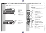
Video Recorder Overview ............................................................ 1-3
Test Equipment / Jigs .................................................................. 1-4
Specifications ............................................................................... 1-4
Operating Hints .......................................................................... 1-11
Service Instructions .................................................................... 1-17
Diagnostic Programme ................................. 2-2
Adjustment Procedures ................................ 3-2
Layout of the PCBs
and Circuit Diagrams ......................... 4-1…4-34
Wiring Diagram ............................................................................ 4-1
Block Circuit Diagram .................................................................. 4-3
• Power Supply ............................................................................ 4-3
• Digital ........................................................................................ 4-4
• Video/Chroma ............................................................................. 4-7
• Audio ......................................................................................... 4-9
• IN/OUT ...................................................................................... 4-9
CP-1: Chassis Board ................................................................. 4-11
• Oscillograms ........................................................................... 4-14
• PW-A:
Power Supply ..................................................... 4-17
Frontend ............................................................. 4-18
• SY-A/MC-A: Drive Control ...................................................... 4-19
• TM-A:
Display ................................................................ 4-22
Keyboard Control ............................................... 4-23
Video/Chroma/Audio (GV 29…) .......................... 4-25
Video/Chroma/Audio (GV 9000…/GV 9300…) ... 4-27
VPS/PDC ............................................................ 4-29
TM-1: Keyboard Control ............................................................. 4-22
TB-1: Socket Board .................................................................... 4-31
• TB-1:
Socket Board (GV 29…) ...................................... 4-32
Socket Board (GV 9000…/GV 9300…) ............... 4-33
Drive Mechanism .............................. 5-16…5-30
Test Equipment / Jigs ................................................................ 5-16
Cleaning ..................................................................................... 5-16
Maintenance and Inspection of the Drive Mechanism ............... 5-17
Names of the Main Mechanical Parts ........................................ 5-17
Checking the Mechanism Mode Positions ................................. 5-19
Operating the Mechanism in the Service Test Mode ................. 5-19
Overview of Operating Modes ................................................... 5-20
Replacing Parts of the Drive Mechanism ................................... 5-21
Adjustments ............................................................................... 5-29
Exploded Views and
Spare Parts Lists ................................ 6-1…6-10
D
Inhaltsverzeichnis
Seite
Allgemeiner Teil ................................. 1-3…1-18
Geräteübersicht ........................................................................... 1-3
Meßgeräte / Meßmittel ................................................................. 1-4
Technische Daten ........................................................................ 1-4
Bedienhinweise ............................................................................ 1-5
Servicehinweise ......................................................................... 1-17
Fehlerdiagnoseprogramm ............................ 2-1
Abgleichvorschriften .................................... 3-1
Platinenabbildungen
und Schaltpläne ................................. 4-1…4-34
Verdrahtungsplan ......................................................................... 4-1
Blockschaltpläne .......................................................................... 4-3
• Netzteil ...................................................................................... 4-3
• Digital ........................................................................................ 4-4
• Video/Chroma ........................................................................... 4-7
• Audio ......................................................................................... 4-9
• IN/OUT ...................................................................................... 4-9
CP-1: Chassisplatte ................................................................... 4-11
• Oszillogramme ........................................................................ 4-14
• PW-A:
Netzteil ............................................................... 4-17
Empfangseinheit ................................................. 4-18
• SY-A/MC-A: Laufwerksteuerung ............................................. 4-19
• TM-A:
Display ................................................................ 4-22
Bedieneinheit ...................................................... 4-23
Video/Chroma/Audio (GV 29…) .......................... 4-25
Video/Chroma/Audio (GV 9000…/GV 9300…) ... 4-27
VPS/PDC ............................................................ 4-29
TM-1: Bedienplatte ..................................................................... 4-22
TB-1: Buchsenplatte .................................................................. 4-31
• TB-1:
Buchsenplatte (GV 29…) ..................................... 4-32
Buchsenplatte (GV 9000…/GV 9300…) .............. 4-33
Laufwerk ............................................. 5-1…5-15
Meßgeräte / Meßmittel ................................................................. 5-1
Reinigung ..................................................................................... 5-1
Wartung und Überprüfung des Laufwerks ................................... 5-2
Bezeichnung der wichtigsten Laufwerksteile ............................... 5-2
Überprüfung der Laufwerksfunktionen ......................................... 5-4
Servicetestmode der Laufwerksfunktionen .................................. 5-4
Übersicht der Laufwerksfunktionen .............................................. 5-5
Auswechseln von Laufwerksteilen ............................................... 5-6
Einstellungen ............................................................................. 5-14
Explosionszeichnungen
und Ersatzteillisten ............................ 6-1…6-10


