background image

deutsch • German • allemand

GV 29…, GV 9000…, GV 9300…

Drive Mechanism

GRUNDIG Service

5 - 19 

k

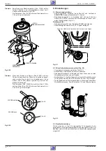
5. Checking the Mechanism Mode Positions

Note:

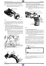
When checking the mechanism mode positions without a
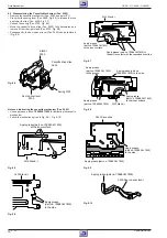
cassette being loaded take care that the opening lever for the
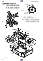
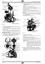
cassette lid (Pos. 040E) is unlocked (Fig. 5.1).

Stand, l 

Lever, lid opener

Cassette mechanism

Fig. 5.1

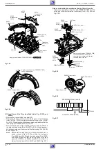
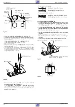
5.1 Determination of the Mode Positions on the Crescent Slide
The marking lines and symbols on the top and bottom side of the
crescent slide (Pos. 60600) show the mechanism mode positions and
their hexadecimal figures.

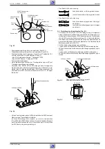
– Checking the drive mechanism from the top:

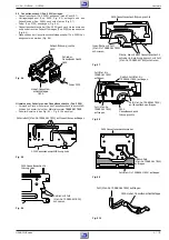
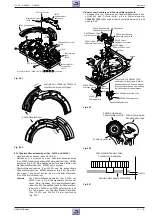
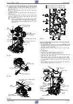
As shown in Fig. 5.2 and 5.3, the respective marking line with
indication of the mechanism mode position can be seen from the
crescent slide (Pos. 60600) at the edge of the mechanism chassis
which is used as the reference line. The hexadecimal figure of the
mechanism mode position can be checked from the hole in the
mechanism chassis.
Note:

No hexadecimal figure is indicated for the EJECT position.
Instead, the hole will be empty. No hexadecimal figure is
indicated for the IN REW mode because it is near the INITIAL
mode and so cannot be indicated either. For the same
reason, there is also no marking line for the INITIAL mode.

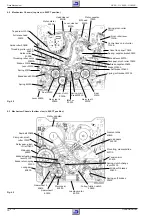
Take this edge as the reference-line

Indicates
HEX DATA

Fig. 5.2

7

1

2

3

4

5

6

FF/REW

STL

IN REW

EJECT

IDL

REV

BRK

PB

EJECTIN REW

REVIEW IDLER STILL/SLOW

PLAY/STOP

BRAKE

FF/REW

EJECT

INITIAL

REVIEW

IDLER

STILL/ SLOW

PLAY/STOP

BRAKE
FF/REW

Fig. 5.3

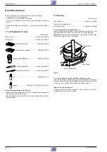
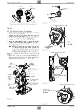
– Checking the drive mechanism from the bottom:

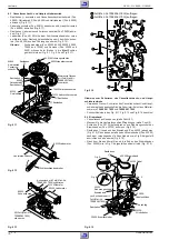
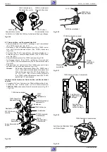
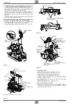
As shown in Fig. 5.4, the respective marking line with indication and
hexadecimal figure of the mechanism mode position can be seen
from the crescent slide (Pos. 60600) at the edge of the mechanism
chassis which is used as the reference line.
Note:

No marking line is provided for the INITIAL mode because
this function is near to the IN REW mode and so cannot be
indicated either.

6

FF/

REW

1

REV

IEW

2

IDL

ER

3

STI

LL

4

BRA

KE

5

PLAY

/STOP

IN

REW

EJC

The edge of the crescent slide mounting
is the reference-line 

Crescent slide mounting

6: FF/REW

4: BRAKE

5: PLAY/STOP

3: STILL

2: IDLER

1: REVIEW

(R-SEARCH)

IN REW

EJC: EJECT

Fig. 5.4

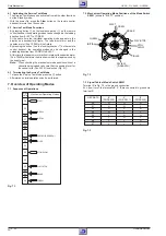
5.2 Operating the Mechanism by Hand
– Dismantle the drive mechanism (see service notes on page 1-17).
– The mechanism operating modes can be checked by rotating the

worm gear (Pos. 60200) at the loading motor (Pos. 60100) or by
rotating the gear wheels (Pos. 60300, 60400 and 60500) with the
worm gear (Pos. 60200) removed (Fig. 4.3).
Note:

The arrow marked on the loading motor (Pos. 60100) indi-
cates the sense of rotation for the worm gear (Pos. 60200)
to reach the EJECT position.

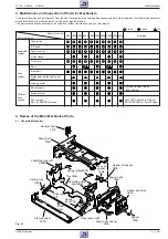
6. Operating the Mechanism in the Service Test Mode

The Service Test Mode is a special function for servicing allowing the
mechanism functions to be checked and the cassette tape to be
ejected forcibly.
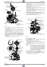
As soon as the VCR is set to the Service Test Mode, the channel
display on the display tube changes to a 2-digit hexadecimal figure
(Fig. 6.1). Some of these figures correspond to the marking lines on the
crescent slide (Pos. 60600) making it possible to check whether the
mechanism mode position is identical with the mode switch S8001.

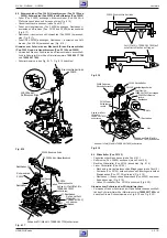
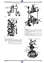
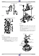
Indicates the
mechanism mode (HEX DATA)

Fig. 6.1

The overview of the operating modes Fig. 7.1 shows the switching
sequence of the individual operating modes.
The respective output signal at the mode switch S8001 can be seen
from the table Fig. 7.3.

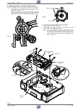
Summary of Contents for G.MH 2300

Page 1: ...fety Materialnr Part No 72010 800 0000 Btx 32700 Materialnummer Part Number 72010 535 1500 nderungen vorbehalten Subject to alteration Printed in Germany W E BS34 E BS35 0599 8002 8012 OGB 8003 8013 h...

Page 2: ...ng 5 16 Maintenance and Inspection of the Drive Mechanism 5 17 Names of the Main Mechanical Parts 5 17 Checking the Mechanism Mode Positions 5 19 Operating the Mechanism in the Service Test Mode 5 19...

Page 3: ...dergabe NTSC Playback S VHS Aufnahme S VHS Record S VHS Wiedergabe S VHS Playback 2 Kopf Head Video 4 Kopf Head Video 2 Kopf Head Audio Rotierender L schkopf Flying Erase Head HiFi Stereo Normalplay L...

Page 4: ...nnel oscilloscope Digital multimeter Millivoltmeter Frequency counter Colour generator AF generator Stabilized power supply Please note the Grundig Catalog Test and Measuring Equipment obtainable from...

Page 5: ...Die Bedienung entnehmen Sie bitte dem jeweiligen Kapitel dieser Bedienungsan leitung Richten Sie die Fernbedienung auf den Videorecorder 8 8 Schaltet den Videorecorder ab Standby 1 0 Ziffern Tasten f...

Page 6: ...t einem EURO AV Kabel verbunden sind Vorbereiten Fernsehger t einschalten Am Fernsehger t den Programmplatz AV f r Recorder Wiedergabe ber das Antennenkabel w hlen Nehmen Sie auch die Bedienungsanleit...

Page 7: ...ngig vom Fernsehger t die Fernseh Programme empfangen und aufzeichnen Deshalb m ssen Sie die Kan le der Fernseh Programme am Videorecorder ein stellen Bei dieser Einstellung wird automatisch auch die...

Page 8: ...EN BEWEGEN L SCHEN NAME W HLEN OK EINGABE INFO ENDE BEWEGEN 1ARD 17 13 2ZDF 18 14 3RTL1 19 15 4RTL2 10 16 5SAT1 11 17 SONDEREINSTELLUNGEN ________________________________________________________ 4 Zei...

Page 9: ...D 01 KANAL C06 FEINEINSTELLUNG DECODER EIN AUS AUSLASSEN EIN AUS W HLEN NDERN MEN TIMER MODE GRUNDEINSTELLUNG W HLEN OK EINGABE INFO ENDE UHRZEIT UND DATUM EINSTELLEN________ Die Digitaluhr des Videor...

Page 10: ...AUTO AUS ABSCHALTEN AUS 2HR 6HR NTSC PB PAL TV NTSC443 AV 2 AV IN DECODER SPERRE EIN11 AUS VCR NO 1 2 W HLEN NDERN OK EINGABE INFO ENDE BESONDERHEITEN__________________________________________________...

Page 11: ...al for more infor mation on operation Direct the remote control at the video recorder 8 8 Switches the video recorder off standby 1 0 Numeric buttons for various entries the 0 button selects the A I p...

Page 12: ...able Preparation Switch the TV set on On the TV set select the AV programme position for video playback via the aerial socket Consult also the user manual of your TV set Adjustment 1 Switch the video...

Page 13: ...elect the AV programme position for video playback on the TV set Programming 1 Press the D D button The AUTO INSTALLATION table appears on the picture screen of the TV set Help If the AUTO INSTALLATIO...

Page 14: ...T MOVE CANCEL NAME SELECT OK ENTER INFO EXIT CHANNEL SORT MOVE CANCEL NAME SELECT OK ENTER INFO EXIT NAME 1ARD 17 13 2ZDF 18 14 3RTL1 19 15 4RTL2 10 16 5SAT1 11 17 SPECIAL SETTINGS____________________...

Page 15: ...NTER INFO EXIT PRESET ARD 01 SYSTEM B G D K CHANNEL C06 FINE TUNING DECODER ON OFF SKIP ON OFF SELECT CHANGE MENU TIMER MODE INSTALLATION SELECT OK ENTER INFO EXIT SETTING THE TIME AND DATE___________...

Page 16: ...R OFF 2HR 6HR NTSC PB PAL TV NTSC443 AV 2 AV IN DECODER CHILD LOCK ON11 OFF VCR NO 1 2 RF SYSTEM B G D K SELECT CHANGE OK ENTER INFO EXIT MODE OSD MODE AUTO OFF OFF POWER OFF 2HR 6HR NTSC PB PAL TV NT...

Page 17: ...bauhinweise 2 1 Laufwerk Steckverbindungen Fig 3 CN181 CN201 CN351 zum Laufwerk l sen Arretierung E Fig 3 des Cassettenschachtes an den beiden Aussparungen F nacheinander l sen und diesen dabei bis An...

Page 18: ...enntrafo benutzen 2 2 Chassis Board Remove the drive mechanism see point 2 1 Disconnect the plug in connections Fig 3 CN701 to the keyboard control unit if necessary Undo 2 screws K Fig 3 L Fig 7 each...

Page 19: ...JECT bei ausgeschaltetem Ger t Standby Lauf werk geht in Stellung INITIAL Ger t geht in Standby Betrieb Ursache Laufwerk Cassettenklappe Code 07 Fehler Cassette kann nicht abgesenkt oder ausgegeben we...

Page 20: ...STOP position EJECT with the VCR switched off Standby Mecha nism changes to INITIAL position VCR switches to Standby mode Cause Mechanism cassette front door Code 07 Fault Lowering or ejecting the ca...

Page 21: ...bleibt der Z hler stehen und ist manuell abgleichbar Manueller Abgleich Mit den Tasten oder ist der Kopfumschaltimpuls auf 6 5 0 5 Zeilen vor den Vertikal Synchronimpulsen einzustellen 6 5 0 5H Zeile...

Page 22: ...r will stop at the set value The value can then be adjusted manually Manual adjustment Use the buttons or to set the head switching pulse to 6 5 0 5 lines before the vertical sync pulses 6 5 0 5H line...

Page 23: ...Circuit Diagrams GRUNDIG Service 4 1 GRUNDIG Service 4 2 ONLY FOR 4 HEAD ONLY FOR 2 HEAD GV9000 9300 GV9000 9300 GV9000 9300 GV29 GV29 GV29 Reference Oscillograms 4 14 AD A 4 29 CP 1 4 11 MC A 4 19 PW...

Page 24: ...701 96 AV CTL 8 SWD PS 12V Q1008 1009 SEGt a l Anoden GRID 1 9 G DIODE OPTION D5102 PW A Back Up FLD DRIVE IC701 KEY SCAN Euro AV 1 ALWAYS 5V FL FLD DATA IN FLD DATA OUT FLD CLK 25 18 24 23 TM A 15 16...

Page 25: ...AKE UP REEL SENSOR 3 T REEL P POWER DOWN POWER CTL TO PW A 10 POWER CTL 9 12 SW DATA 0 SW DATA 2 XI XO 38 37 OSCI OSCO X3002 14 32MHz PB L YCA MUTE PB L YCA MUTE 44 62 TO VA A CFG ALWAYS 5V A MUTE 78...

Page 26: ...AGC FM MOD W D CLIP FM DEM SUB LPF DOUBLE LIM DETAIL EMPHA CLAMP 21 20 1 2 SERIAL DECODER 22 23 24 Chara IMS 26 SYNC SEP Y LPF Y N R NL DE_EMP FBC PIC CTL ANR Y C MIX R P PB_Y PB_C II PLL 28 6DB AMP...

Page 27: ...EURO AV DECODER VIDEO IN EURO AV BLANKING CONTROL EURO AV VIDEO OUT CH VIDEO IN AUDIO IN CN871 AUDIO OUT RGB BLUE RGB GREEN RGB RED CONTROL CH AUDIO IN CN872 CH AUDIO OUT Q8604 PB L 6dB 6dB CLAMP CLAM...

Page 28: ...PCBs and Circuit Diagrams GV 29 GV 9000 GV 9300 4 11 GRUNDIG Service 4 12 GRUNDIG Service CP 1 Chassisplatte Chassis Board Ansicht von der L tseite konventionelle Best ckung View of Solder Side Conve...

Page 29: ...C1042 J 9 C1043 H 9 C1045 H 9 C1046 G 9 C1047 H 9 C1048 G 8 C1049 I 8 C1050 H 8 C1051 H 8 C1052 I 9 C1053 E 11 C1054 E 10 C1055 H 9 C1056 H 8 C1059 J 8 C1060 G 9 C1061 H 12 C1062 I 8 C1063 G 8 C1064 H...

Page 30: ...IC101 41 46 REC PLAY Ch1 100mV M 20 s IC101 43 45 REC PLAY Ch1 100mV M 20 s IC101 51 61 REC PLAY Ch1 100mV M 20 s IC101 57 59 REC PLAY Ch1 100mV M 20 s IC101 71 72 PLAY Ch1 100mV M 20 s IC101 71 72 R...

Page 31: ...Platinenabbildungen und Schaltpl ne Layout of PCBs and Circuit Diagrams CP 1 Chassisplatte Chassis Board Ansicht von der L tseite View of Solder Side GRUNDIG Service 4 15 GRUNDIG Service 4 16 A B C D...

Page 32: ...Bs and Circuit Diagrams GV 29 GV 9000 GV 9300 4 17 GRUNDIG Service 4 18 GRUNDIG Service PW A Chassisplatte Netzteil Chassis Board Power Supply SY A Chassisplatte Empfangseinheit Chassis Board Frontend...

Page 33: ...nd Schaltpl ne Layout of PCBs and Circuit Diagrams GRUNDIG Service 4 19 GRUNDIG Service 4 20 SY A MC A Chassisplatte Laufwerksteuerung Chassis Board Drive Control Reference Oscillograms 4 14 AD A 4 29...

Page 34: ...e r c s n o o t l a n g i s t u p n i o e d i V t i u c r i c o v r e s H L I O Name No Signal Function H L I O Name No Signal Function 1 5 2 D D V V 5 s y a w l A 2 5 C C F A 3 5 F P L C F A 4 5 C N...

Page 35: ...inheit Chassis Board Keyboard Control GV 29 VPS GV 29 VPS 5 GV 9000 SV GV 9000 SV 5 GV 9300 SV GV 9300 SV 5 D7001 X X X X D7003 X X D7005 D7006 X X X D7008 X X X X D7011 X X X D7012 X X X X D7014 X X...

Page 36: ...pl ne Layout of PCBs and Circuit Diagrams GV 29 GV 9000 GV 9300 GV 29 VA A Chassisplatte Chassis Board Video Chroma Audio IC101 LA71590M 2 EURO AV TP 182 4 25 GRUNDIG Service 4 26 GRUNDIG Service Refe...

Page 37: ...abbildungen und Schaltpl ne Layout of PCBs and Circuit Diagrams IC101 LA71590M TP 182 GV 9000 GV 9300 VA A Chassisplatte Chassis Board Video Chroma Audio GRUNDIG Service 4 27 GRUNDIG Service 4 28 Refe...

Page 38: ...9000 GV 9300 GV 29 AD A Chassisplatte Chassis Board Interface USED ONLY 2 EURO AV GV 9000 GV 9300 AD A Chassisplatte Chassis Board Interface TC A Chassisplatte Chassis Board VPS PDC IC141 LC74793JM VP...

Page 39: ...8501 B 2 J8502 B 3 J8503 B 1 J8504 B 2 J8505 A 3 J8506 B 2 J8507 B 3 J8508 A 3 J8509 C 1 J8510 C 2 J8511 D 2 J8512 B 1 J8513 A 4 J8514 B 4 J8515 A 1 J8516 B 3 J8517 B 4 J8518 B 4 J8519 E 3 J8531 B 2 J...

Page 40: ...nd Schaltpl ne Layout of PCBs and Circuit Diagrams GV 29 GV 9000 GV 9300 GV 9000 GV 9300 TB 1 Buchsenplatte Socket Board IC861 LA7148M INTERFACE 4 33 GRUNDIG Service 4 34 GRUNDIG Service Reference Osc...

Page 41: ...h darauf da kein Staub oder Fremdk rper auf die zu schmierenden Stellen gelangen 2 Reinigung Materialnummer Methylalkohol handels blich Reinigungstuch Fensterleder oder weiches fusselfreies Tuch hande...

Page 42: ...nd berpr fung des Laufwerks Um volle Funktionsf higkeit des Laufwerks zu gew hrleisten und berm igem Verschmutzen vorzubeugen empfehlen wir die in der Tabelle aufgelisteten Wartungsarbeiten und Tests...

Page 43: ...or 60100 Riemenscheibe Reibkupplung 20500 Fig 4 2 Fig 4 3 Bandtrommel kpl 11000 Hauptl schkopf 50100 F hrungsrolle 5060B F delschlitten rechts 5060A F hrungsrolle 5050B F delschlitten links 5050A Brem...

Page 44: ...ezeigt werden kann Aus diesem Grund ist auch keine Markierungs linie f r den INITIAL Modus vorgesehen Laufwerk von unten Wie in Fig 5 4 dargestellt kann die jeweilige Markierungslinie mit der Bezeichn...

Page 45: ...icht Der Capstanmotor Pos 70500 dreht sich in der Richtung in der das Band von der Abwickelspule gespult wird Hinweis Soll die berpr fung der Laufwerksfunktionen ohne Cassette erfolgen mu darauf geach...

Page 46: ...itionen ausrichten Funktions wahlschalter 8 1 Cassettenschacht Pos 0090 ausbauen 2 Schrauben Pos 6073 herausschrauben Fig 8 3 Den Cassettenschacht Pos 0090 an der R ckseite etwas anhe ben nach hinten...

Page 47: ...as Schmiermittel mit der Materialnummer 75988 061 7800 Schmierhinweise in den Fig 8 5 Fig 8 10 beachten 0100 Cassettenschachtf hrung links Schmierfett Mat Nr 75988 061 7800 auf Innenfl chen auftragen...

Page 48: ...Sie zum Schmieren des Cassettenschacht und Haupt schieberantriebs ausschlie lich die Schmiermittel mit den Material nummern 75988 061 7800 und 75988 061 7900 Schmierhinweise in den Fig 8 11 Fig 8 13 u...

Page 49: ...se mit l Mat Nr 75988 061 7700 schmieren Achse mit Fett Mat Nr 75988 061 7800 schmieren Achse mit Fett Mat Nr 75988 061 7800 schmieren Fig 8 17 30400 Bremsschieber links Fett Mat Nr 75988 061 7800 auf...

Page 50: ...nd Brems steuerhebel Pos 31000 herausnehmen Fig 8 22 Bremsr ckholfeder Pos 31300 und Getriebefeder Pos 31200 aush ngen Fig 8 22 Rasthaken L dann Rasthaken M ausrasten und Brems und Getriebehebel Pos 3...

Page 51: ...5040C Fig 8 27 F delschlitten rechts 5060A F delschlitten links 5050A Bandzugf hler Steuerhebel 40400 60710 Schraube 60700 Hauptschieber abdeckung 60600 Hauptschieber Bremsr ckholfeder 31300 b b a a...

Page 52: ...rsehebelfeder Pos 50800 in das Loch T des Laufwerkchassis stecken und das andere Ende am Reversehebel Pos 50700 einh ngen sie he Fig 8 30 Das Andruckrollenkurvenrad Pos 70300 und das Zwischenzahnrad P...

Page 53: ...X Wert einstellen siehe Punkt 9 Einstellungen 50210 Schraube 50200 A W Kopfeinheit Loch Stift U V Fig 8 36 8 13 Bandtrommel Zwei Schrauben Pos 30000 herausschrauben Stator des Motors Pos 22000 abnehm...

Page 54: ...10g cm liegen Taste w hrendderWiedergabedr cken Drehmomentdeslinken Wickeltellers messen Es mu zwischen 115 und 180g cm liegen Fig 9 2 9 3 Bandlaufeinstellung Wurde eines der in Fig 9 3 dargestellten...

Page 55: ...sind die Umlenkrollen Pos 5050B und 5060B des linken und rechten F delschlittens mit dem Einstellschraubendreher so einzustellen da die Amplitude der FM Pakete m glichst geradlinig ist Das Band l uft...

Page 56: ...e Other lubricants may cause malfunctions in the mechanism Be careful to keep the points surfaces to be lubricated free of dust or foreign bodies 2 Cleaning Part Number Methyl alcohol commonly availab...

Page 57: ...full function and performance from the video recorder and to avoid it getting excessively dirty we recommend that the maintenance work and checks listed in the table below be carried out at regular i...

Page 58: ...010C Pinch roller lever 7010A Control lever pinch roller 7010B Cass lid opener 70400 Spring capstan brake 30900 Load lever 50700 Rack gear pinch roller 70200 Brake capstan 30800 Brake t 30200 Soft bra...

Page 59: ...ine with indication and hexadecimal figure of the mechanism mode position can be seen from the crescent slide Pos 60600 at the edge of the mechanism chassis which is used as the reference line Note No...

Page 60: ...he display as a hexadecimal figure The tape drum motor and the capstan motor Pos 70500 will not rotate By pressing the button on the local keyboard or D on the remote control handset the operating mod...

Page 61: ...de Fig 8 1 and 8 2 Fig 8 1 Fig 8 2 Align the positions Mode switch 8 1 Removing the Cassette Mechanism Pos 0090 Undo 2 screws Pos 6073 Fig 8 3 Lift the back of the cassette mechanism Pos 0090 by a sma...

Page 62: ...ease part no 75988 061 7800 for lubricating the cassette mechanism Follow the instructions given in Fig 8 5 Fig 8 10 0100 Stand l Apply grease part no 75988 061 7800 at the inner surface Fig 8 5 0100...

Page 63: ...00 Loading motor 60200 Worm gear 61100 Damper Apply grease part no 75988 061 7900 to the shaft hole Apply grease part no 75988 061 7800 Fig 8 13 Apply grease part no 75988 061 7800 Apply grease part n...

Page 64: ...Clamp Clamp 30200 Brake t Clamp Clamp Clamp 20200 Idler Apply oil part no 75988 061 7700 to the shaft Apply grease part no 75988 061 7800 to the shaft Shaft part no 75988 061 7800 G H H H G G Fig 8 17...

Page 65: ...clamp J then clamp K and remove the brake control lever Pos 31000 Fig 8 22 Detach the brake return spring Pos 31300 and the clutch change lever spring Pos 31200 Fig 8 22 Disengage clamp L then clamp M...

Page 66: ...e mounting 60600 Crescent slide 31300 Brake return spring b b a a c d d Apply grease part no 75988 061 7800 to Clamp Hole Pin Tension arm 40400 Fig 8 23 60600 Crescent slide Apply grease part no 75988...

Page 67: ...f the mechanism chassis and hook the other end to the load lever Pos 50700 as shown in Fig 8 30 Position the cam gear of the pinch roller Pos 70300 and the relay gear of the pinch roller Pos 70600 as...

Page 68: ...ath and tracking position X value refer to point 9 Adjustments 50210 Screw 50200 R P Head assy Hole Pin U V Fig 8 36 8 13 Tape Drum Undo two screws Pos 30000 remove the motor stator Pos 22000 and the...

Page 69: ...heck that it is between 60 and 110g cm Press the button in PLAY mode Measure the torque of the left reel The value must lie between 115 and 180g cm Fig 9 2 9 3 Adjusting the Tape Path Whenoneofthepart...

Page 70: ...s 5050B and 5060B of the left and right threading roller unit with the adjustment screwdriver so that the amplitude of the FM pack ages is as flat as possible Tape rides over the top edge turn the lef...

Page 71: ...0A 5050A 5050B 1200 0090 0100 040B 040D 040D 040E 040F 0300 0500 0600 0700 0200 040C 040A 20100 50110 50100 20110 20110 10400 10400 20130 20120 61000 60900 40100 40200 40300 20200 20600 30100 30300 30...

Page 72: ...GV 9000 GV 9300 6 2 GRUNDIG Service 2 70500 20510 20500 20400 20310 2030A 2030B 1010D 1010B 31300 31100 31000 31200 20800 70600 60510 60500 60800 60400 60300 60200 61100 60100 30400 30500 60700 60600...

Page 73: ...Ersatzteillisten Exploded Views and Spare Parts Lists GRUNDIG Service 6 3 3 0007 000 0026 000 0025 000 0034 000 0160 000 0006 100 0006 500 0006 600 0006 200 0006 700 0006 000 0050 000 0070 000 0008 0...

Page 74: ...ventuell abweichenden landesspezifischen Vorschriften The regulations and safety instructions shall be valid as provided by the Safety Service Manual part number 72010 800 0000 as well as the respecti...

Page 75: ...rschriften The regulations and safety instructions shall be valid as provided by the Safety Service Manual part number 72010 800 0000 as well as the respective national deviations Ersatzteilliste Spar...

Page 76: ...L P E 72010 535 1500 SERVICE MANUAL D GB F SERVICE MANUAL D GB F X SIEHE GESONDERTE E LISTE X SEE SEPARATE PARTS LIST Ersatzteilliste Spare Parts List GV 9300 SV 5 VIDEO MATERIAL NR PART NO 77400 877...

Page 77: ...DRIVE GEAR LEFT ASSY 50400 2 75988 061 5100 ANTRIEBSRAD RECHTS KPL DRIVE GEAR RIGHT ASSY 50500 1 75988 061 1900 FAEDELSCHLITTEN LINKS KPL ROLLER UNIT LEFT ASSY 50600 1 75988 061 2100 FAEDELSCHLITTEN R...

Page 78: ...75981 309 2800 DR 10UH 10 POS NR MATERIAL NR BEZEICHNUNG POS NO PART NUMBER DESCRIPTION POS NR MATERIAL NR BEZEICHNUNG POS NO PART NUMBER DESCRIPTION Btx 32700 NDERUNGEN VORBEHALTEN SUBJECT TO ALTERAT...

Page 79: ...9 011 0000 ALL PARTS NOT LISTED REFER TO PARTS LIST LP CHASSIS 27599 011 0000 D 07021 75954 036 8200 DIODE GMB01BTM1 Ersatzteilliste Spare Parts List LP CHASSIS CP A GV 9300 SV 5 VIDEO MATERIAL NR PAR...

Page 80: ...SS 133 D 08607 83092 301 3300 DIODE 1 SS 133 D 08608 75988 060 6800 Z DIODE MTZJ 5 6 A D 08609 75988 060 6800 Z DIODE MTZJ 5 6 A D 08610 75988 060 6800 Z DIODE MTZJ 5 6 A D 08611 75988 060 6800 Z DIO...

Reviews: