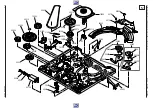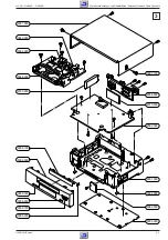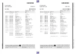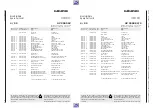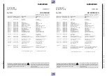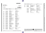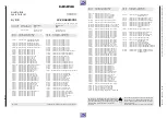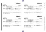
Drive Mechanism
GV 29…, GV 9000…, GV 9300…
k
5 - 26
GRUNDIG Service
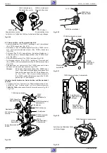
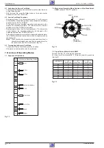
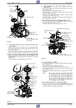
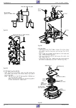
Notes on lubricating the mechanical parts of the roller units
– Always use the grease with part number 75988 061 7800 for lubri-
cation and follow the lubrication instructions given in Fig. 8.25 and
Fig. 8.28!
5040A
Gear, load t
5040B
Spring, load t
5040C
Lever, load t
5030A Gear, load s
5030B Spring, load s
5030C Lever, load s
5060A
Threading
roller
unit t
Incline pin
Incline pin
5060B Guide roller
5050B
Guide roller
5050A Threading
roller unit s
Shaft
Shaft
Shaft
Shaft
Clamp
Apply grease (part no. 75988 061 7800)
to the shaded shafts and parts of
the mechanism chassis and the sur-
rounding area of the rail
Q
Fig. 8.25
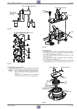
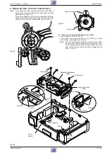
5040A Gear, load t
5030A Gear, load s
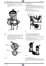
Align the position
Fig. 8.26
5030A/5040A Gear, load s/t
0.5mm
Load lever 5030C/5040C
Fig. 8.27
Threading roller
unit, r 5060A
Threading
roller unit, l
5050A
c
N
O
P
60710
Screw
60700
Crescent slide
mounting
60600
Crescent slide
31300
Brake return
spring
b
b
a
a
c
d
d
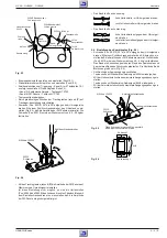
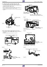
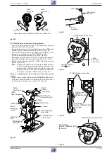
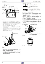
Apply grease (part no. 75988 061 7800) to , , , .
Clamp
Hole
Pin
Tension arm
40400
Fig. 8.23
60600 Crescent slide
Apply grease (part no. 75988 061 7800)
to the shaded part
5mm
10mm
Fig. 8.24
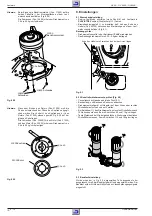
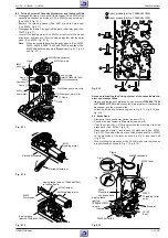
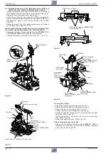
8.10 Load Gears of the Threading Roller Units (Pos. 5030A and
5040A)
– Remove the crescent slide (see point 8.9).
– Disengage the clamp
Q
and remove the load gear of the threading
roller unit (Pos. 5030A) and the detached load spring (Pos. 5030B,
Fig. 8.25). When disassembling these components, take care that the
load spring (Pos. 5030B) does not jump off.
– Remove the load gear of the threading roller unit (Pos. 5040A) and
the detached load spring (Pos. 5040B, Fig. 8.25). When disassem-
bling these components take care that the load spring (Pos. 5040B)
does not jump off.
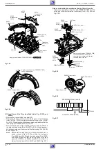
Note:
Reassemble the load gears (Pos. 5030A and 5040A) in the
position shown in Fig. 8.26. When fitting the load gears
(Pos. 5030A and 5040A) and the load springs (Pos. 5030B
and 5040B) make sure that the spring hooks of the load
gears (Pos. 5030A and 5040A) protrude 0.5mm from the
plates of the load levers (Pos. 5030C and 5040C, Fig. 8.27).

