GENO
®
-flushing compressor 1988 K
Order no. 015 151 963-inter Created: KONS-gmei-mrie G:\BA-151963-INTER_GENO-SPUELKOMP-1988_K.DOC
36
2.4 Additional assembly of an optional system divider on the flushing compressor for
disinfection of pipelines
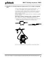
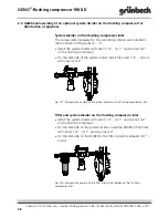
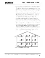
System divider on the flushing compressor inlet
The components necessary for this connection version are included in
the connection fitting cases ¾" - 2".
Install the system divider with insert 1 ¼" - IG 1" and cap nut G 2"
on the flushing compressor.
On the inlet side of the system divider install the insert 1 ¼" - 24 mm
with cap nut G 2".
Fig. D-7: Example of assembly of the system divider on the flushing compressor inlet
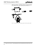
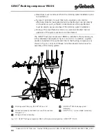
Filter and system divider on the flushing compressor inlet
Install the system divider with insert 1 ¼" - IG 1" and cap nut G 2"
on the flushing compressor.
On the inlet side on the system divider, install the BOXER K fine filter
with insert 1 ¼" - IG 1" and cap nut G 2".
On the inlet side on the BOXER K fine filter, install the adapter IG 1" -
24 mm.
Fig. D-8: Example of assembly of the filter and system divider on the flushing
compressor inlet


